


Installation Instructions
15
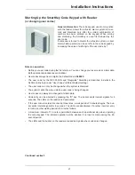
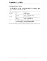
Function Test for the SPE Blocking Element and Reader
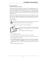
Turning on the power supply
x
Make sure that bridge B1 on the control unit is connected before turning on the power supply.
x
Turn on the power supply.
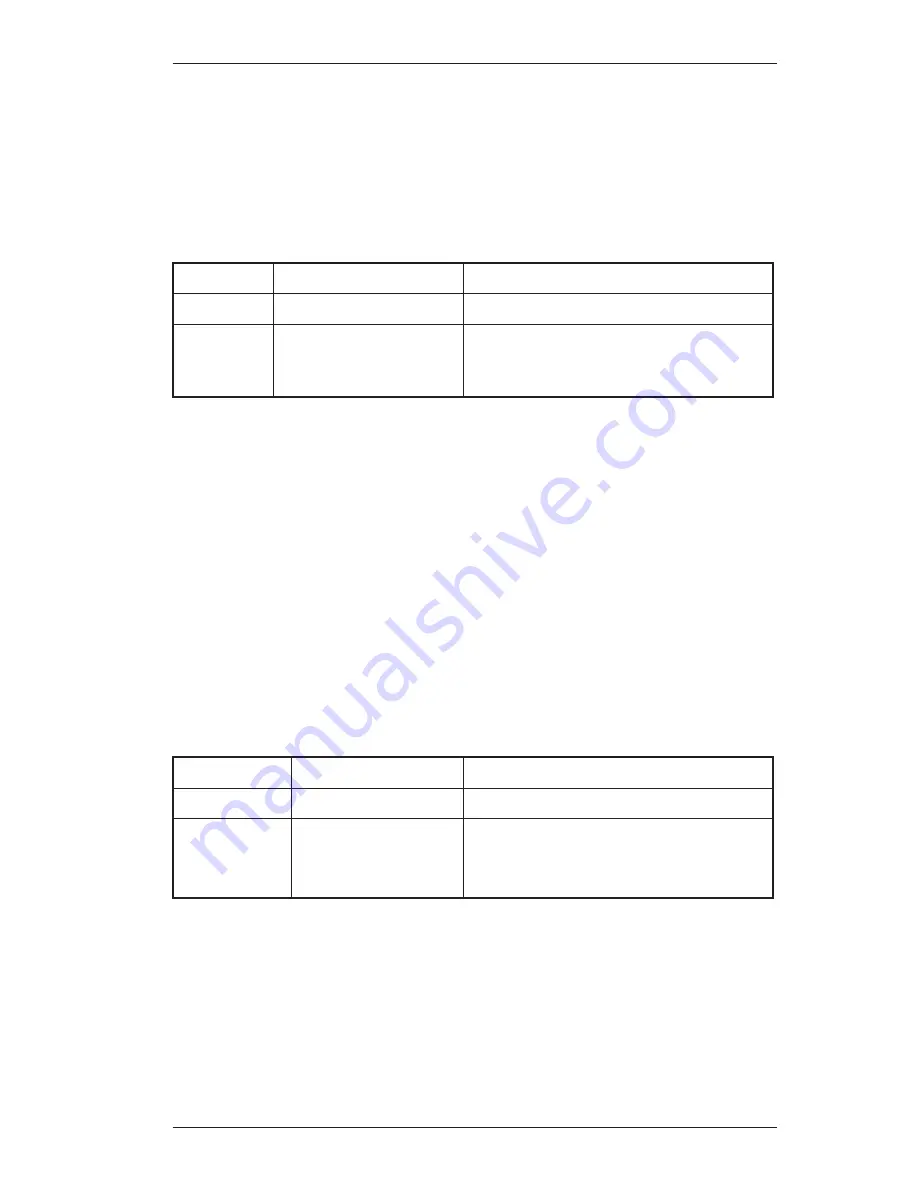
The yellow LED on the control unit displays the system's status as follows:
Yellow LED
Status
Required action
Off
System is OK
None
On
Electronic defect
Turn the power supply off and then back on.
Replace the control unit if the LED is still acti-
vated.
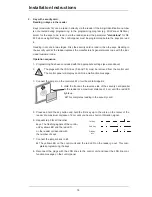
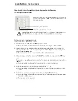
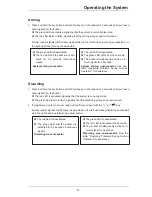
Function test
1. Remove the jumper from B1 and connect it to B3 on the control unit.
¨
The SPE blocking element bolt engages. The yellow LED on the control unit lights up. The
red and green LEDs on the reader light up. The reader buzzer sounds for 5 seconds.
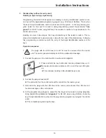
2. Remove the jumper from B3 on the control unit.
¨
The SPE blocking element bolt disengages. The LEDs on the control unit and the reader
are go out.
3. Repeat steps 1 - 2 with the door closed to check the precise insertion of the SPE blocking e-
lement's bolt into the bolt-hole.
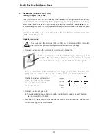
4. Reconnect the jumper to bridge B1 on the control unit once you have completed the function
test.
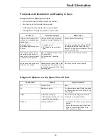
The yellow LED on the control unit's circuit board indicates the system's status as follows:
LED Status
Required
action
Off
System is OK
None
1 flash
Bolt will not engage
or disengage
Check the SPE blocking element and the
bolt-hole for correct installation and electrical
connection.
Repeat the test.


