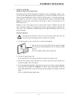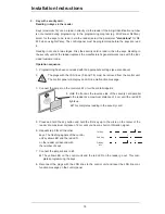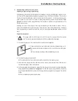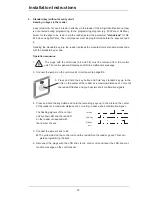
Installation Instructions
8
Installing System Components
Note the following during installation:
x
Used shielded cables only.
x
The usual precautionary measures for handling C-MOS technology apply to han-
dling the circuit boards and to soldering work. Wear a grounded wrist strap when
working on the control panel.
Mounting the control unit
x
Mount the control unit to the wall. When choosing a position to mount the unit,
please note that the reader and SPE blocking element are equipped with a 6 m molded
cable that must not be lengthened.
Installing the reader
x
Install the reader according to the enclosed installation notes.
If you are installing the reader close to other systems with proximity scanners, please
make sure that a distance to these systems of at least 0.5 m is maintained.
The installation height should be at least 1.2 m and preferably recessed mounted. The
reader is molded and completely resistant to environmental influences. Do not fit the
reader cover until you have performed all the function tests. Removing the cover after it
has been fitted will cause damage to the cover. The reader is equipped with a 6 m mol-
ded cable that must not be lengthened.
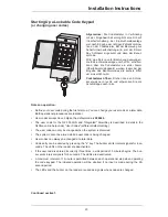
Installing the code keypad
x
The code keypad must be installed outside of the security area close to the assigned door
(next to the reader because of the LED and buzzer) and protected from atmospheric
conditions. Make sure that the code keypad is not visible to other persons during use.
Install the code keypad in accordance with the installation instructions enclosed with
the device. The SmartKey code keypad is equipped with a 6 m molded cable that must
not be lengthened.
Important information for lockable code keypad:
Connect points LF1 and LF2 with a
solder bridge as described in the code keypad installation instructions if you want to
enable user codes to be changed using the keypad.
!
!
!
!


