202
en | System menus and dialogs
Security Escort
2018.03 | SE3v1.0 | DOC
Technical Reference Manual
Robert Bosch (SEA) Pte Ltd
Notice!
The illuminated LED indicate to the service person standing near the device that the SE
receiver is actually the one currently in the setup mode. If the LED of the designated SE
receiver is not illuminated, there is probably an error in the switch settings of the SE receiver
or an error in the address in the
Transponder database
. To help resolve such problems, the
person at the Central Console can command any device to illuminate its LED and/or sound its
horn.
If the SE receiver in the setup mode detects the maintenance alarm, and if the received signal
is the strongest of all SE receivers, the horn on the SE receiver sounds briefly and the LEDs go
off. This indicates the SE receiver is functioning properly and the SE receiver’s address is set
correctly in the
Transponder database
, as well as on the SE receiver’s switches.
The Central Console also confirms the successful setup with an audible and text message. The
[Abort setup for this
MUX point]
button disappears, and is replaced by
[Test on this MUX
point SUCCESSFUL]
button. Click the button to conclude the test of this point.
10.4.9
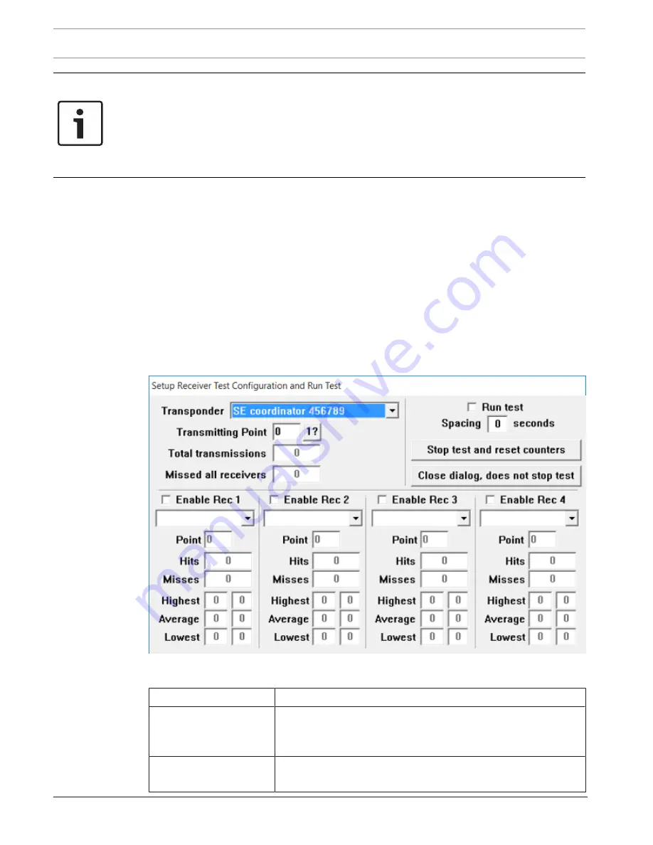
Receiver test
Use this dialog to set up and monitor four SE receivers, and listen to one SE receiver
transmitting with its buddy check transmitter. Normally, the function is for engineering
evaluation of new transmitter and SE receiver designs, but it can be used to test SE receiver
boards and locations in a working system.
Figure
10.26: Receiver test dialog
Element
Usage/Description
Transponder
Select the SE coordinator for the transmitting point and each
receiving point. They can be on the same or different SE
coordinators.
Transmitting Point
Select the point (SE receiver) on the selected SE coordinator to
generate the transmissions.
Summary of Contents for SE3000 Series
Page 1: ...Security Escort SE3000 Series en Technical Reference Manual ...
Page 2: ......
Page 255: ......


