background image

Security Escort Point Tracking Transmitter

Installation and Setup | en

11

Robert Bosch (SEA) Pte Ltd

Installation Manual

2018.01 | SE3v1.0 | DL

Figure


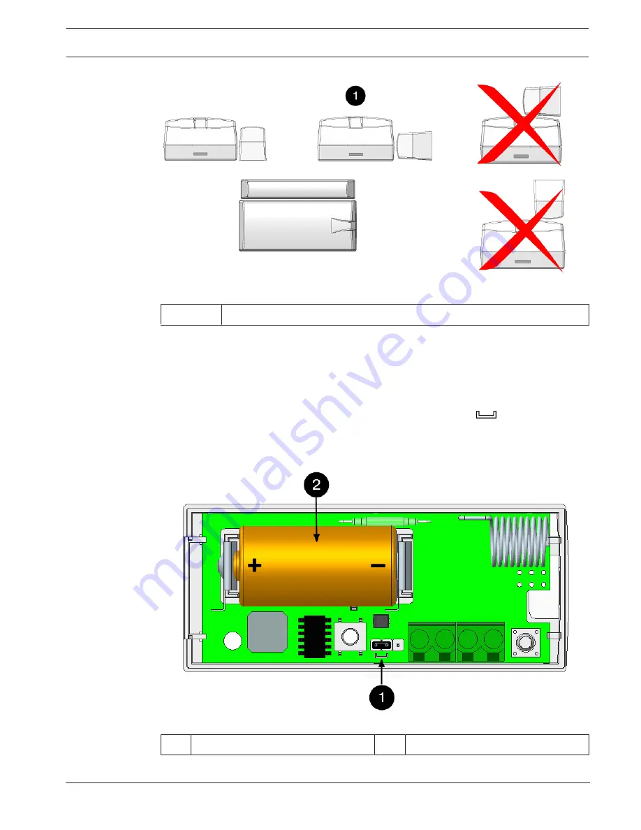
3.7: Mount the magnet

1 End view from the opening end

3.2

Powering up the point transmitter

The SEC-3402 series can be powered up either by 3V battery or 12 VDC input, depending on
the setting of the jumper.

3.2.1

3V battery

1.

Check that the jumper is set over the jumper pins marked by the 

 symbol. This is the

default factory setting on the point transmitter.

2.

Install the recommended type of battery: Duracell® DL123A, Energizer® EL123AP or
Panasonic® CR123A. Be sure to observe the polarity.

Figure


3.8: Install battery

1 Jumper setting

2 Battery

Summary of Contents for SEC-3402-304

Page 1: ...Security Escort Point Tracking Transmitter SEC 3402 Series en Installation Manual ...

Page 2: ......

Page 3: ...mounting 8 3 1 2 Mounting without the mounting plate 10 3 1 3 Mounting the magnet 10 3 2 Powering up the point transmitter 11 3 2 1 3V battery 11 3 2 2 12 VDC input 12 3 3 Setting up magnetic or external contacts 12 4 Enabling and Disabling Features 14 4 1 Default dip switch setting 14 4 2 Setting the radio frequency RF 14 4 3 Enable disable the auto track 15 4 4 Enable disable the displacement de...

Page 4: ... provided for in the said license agreement All software is provided AS IS The sole obligation of BOSCH SECURITY SYSTEMS shall be to make available all published modifications that correct program problems are published within one 1 year from the date of shipment The software is intended for use only with the hardware specified in this manual and in the absence of other software Concurrent use wit...

Page 5: ...nit has been exposed to water and or inclement weather rain snow etc If the unit does not operate normally when following the operating instructions Adjust only those controls specified in the operating instructions Improper adjustment of other controls may result in damage and require extensive work by a qualified technician to restore the unit to normal operation If the unit has been dropped or ...

Page 6: ...ble for compliance could void the user s authority to operate the equipment This equipment has been tested and found to comply with the limits for a Class B digital device pursuant to Part 15 of the FCC Rules These limits are designed to provide reasonable protection against harmful interference in a residential installation This equipment generates uses and can radiate radio frequency energy and ...

Page 7: ...s available in the following models Transmitter Model Description SEC 3402 304 Point tracking transmitter 303 304MHz SEC 3402 433 Point tracking transmitter 433MHz 2 1 Supervision Supervision is provided by transmitting a low power level signal to the receiver every 60 min if there is no other activity SEC 3402 series send battery status information to the system 2 2 Auto tracking Once an alarm is...

Page 8: ...ge of the unit Placing the point transmitter on ferrous metal iron or steel surfaces can affect operation of the magnetic contact 3 1 1 Recommended mounting 1 Position the mounting plate over the desired location and attach it with the supplied screws Figure 3 1 Attach mounting plate 1 Release tab 2 Mounting holes 2 Open the cover using a screwdriver Figure 3 2 Open cover 1 Insert screwdriver and ...

Page 9: ...v1 0 DL Figure 3 3 Slide point transmitter over base 5 The point transmitter can be released from the base by pressing the release tab with a small screwdriver or a paper clip 6 For higher security installations mount the transmitter using the tamper screw provided Figure 3 4 Mount transmitter using tamper screw 1 Tamper screw ...

Page 10: ...er to remove the board Figure 3 5 Lift printed circuit board 3 Rock the board gently to loosen the battery clips from the case and slide the board away from the mounting clips near the area where the cover connects to the base 4 Mount the point transmitter in the desired location taking note the magnet needs to be on the same side of the case as the reed switch Figure 3 6 Mount point transmitter i...

Page 11: ...EC 3402 series can be powered up either by 3V battery or 12 VDC input depending on the setting of the jumper 3 2 1 3V battery 1 Check that the jumper is set over the jumper pins marked by the symbol This is the default factory setting on the point transmitter 2 Install the recommended type of battery Duracell DL123A Energizer EL123AP or Panasonic CR123A Be sure to observe the polarity Figure 3 8 I...

Page 12: ... VDC source to the connector of the transmitter Figure 3 9 12 VDC input 1 Jumper setting 2 12 VDC in 3 3 Setting up magnetic or external contacts The SEC 3402 series has the capacity to monitor magnetic and or dry external contacts External Normally Closed NC or external Normally Open NO contacts can be monitored Recommended cable 18 AWG 20 ft 6 m EOL resistor 1 Mega ohms Notice If not using exter...

Page 13: ...nsmitter Installation and Setup en 13 Robert Bosch SEA Pte Ltd Installation Manual 2018 01 SE3v1 0 DL Figure 3 10 Magnet optional typical NC wiring 1 Magnet bar 2 EOL resistor Figure 3 11 Magnet optional typical NO wiring 1 EOL resistor ...

Page 14: ... Auto track every 7 seconds 3 Displacement Detection 4 Reed Switch 5 Buzzer 6 Not Used Notice Remove the battery before setting the dip switches Changes to the dip switches should be performed by administrators only 4 1 Default dip switch setting The default setting of the SEC 3402 series dip switch is as follows Default Setting Switch Number on Dip Switch 1 2 3 4 5 6 not used Switch Position OFF ...

Page 15: ...placement detection Enable or disable the displacement detection feature by setting switch number 3 on the dip switch Set switch number 3 to the OFF position to disable the displacement detection feature Set switch number 3 on the dip switch to the ON position to enable the displacement detection feature Once enabled any movements of the transmitter will send a signal back to the Central Console D...

Page 16: ...switch 4 7 Factory reset Factory reset should be performed by administrators only Set all the dip switches to the OFF position While pressing the Test button the transmitter resets after inserting the battery If reset is successful there will be 3 slow consecutive beep tones every 1 second If reset is unsuccessful there will be 2 slow consecutive beep tones every 1 second Refer to the following li...

Page 17: ...tion Using the Central Console software enable or disable the features accordingly and send the configuration to the transmitter Please refer to the Security Escort Technical Reference Manual for further details 4 10 Testing the transmitter Test your transmitter by standing within sight of a receiver Press the Test button for 3 seconds until the transmitter emits 3 short beep tones A test transmis...

Page 18: ...g Transmitter Firmware Notice Please note that this feature is only applicable to SEC 3402 433 transmitter model Transmitter firmware can be upgraded wirelessly via a dedicated coordinator using the Utility Tool of the Security Escort software For more information on the usage of Utility Tool please refer to the Security Escort Technical Reference Manual ...

Page 19: ......

Page 20: ...Bosch Sicherheitssysteme GmbH Robert Bosch Ring 5 85630 Grasbrunn Germany www boschsecurity com Bosch Sicherheitssysteme GmbH 2018 Robert Bosch SEA Pte Ltd 11 Bishan Street 21 573943 Singapore Singapore ...

Reviews: