1 695 108 074
2016-07-27
|
Robert Bosch GmbH
36 | Start Line TCE 420 | Initial commissioning
en
7. Operation
!
The following information must be read, and will be
helpful to the operator to simplify the steps needed
for operation and reduce unnecessary trouble.
7.1
Safety notice
!
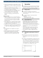
The TCE 420 is intended to be used only to
mount/demount passenger car tires (see the section
"Technical data").
!
If an accident happens, shut off the TCE 420
immediately.
$
Disconnect mains plug.
$
Turn off compressed air supply.
7.2
Check before use
1.
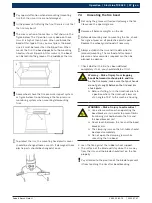
Before operating the TCE 420, always run the
bead breaking cylinder back and forward while
observing the lubricator to make sure it starts
feeding oil to the air passage. After you confirm
that the lubricator works normal, you can guarantee
each part of the air route system under perfect
lubrication.
2.
Check the maintenance unit to ensure that the
pressure indicated on the pressure gauge of the
pressure-limiting valve is not less than 8 bar.
3.
Check whether the power supply connection is
correct.
7.3
Information about special rims and
tires
i
Special process to be need for some special tires,
which different from the normal demount/ mount
process.
i
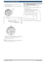
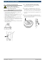
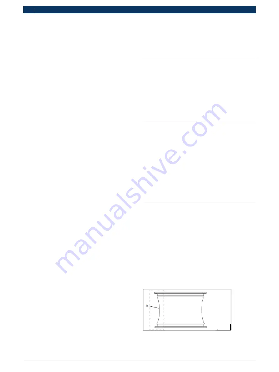
As shown in the figure below, some alloy rims have a
very shallow rim channel in the center of the rim. Or
the rim channel has no depression. These rims do
not meet the safety regulations for vehicular traffic
and transportation. In some countries, these types
of rim/wheel are not allowed in the market.
Depress the clamping jaws control pedal 7-2 to the
second position and the clamping jaws immediately
stop.
Depress the clamping jaws control pedal 7-2 to the
third position and the clamping jaws close.
When the mounting arm is at the innermost position,
it is released and tool head will drop.
When the mounting arm is at the middle position, it
is released and the tool head will move up.
When the mounting arm is at the outermost
position, the mounting arm and tool head are
locked.
Maintenance unit
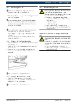
Pressure-limiting valve 13-1: Pull out the knob on
the top of the pressure-limiting valve A. Clockwise/
counterclockwise turning can adjust the supply
pressure to the TCE 420. Press down the knob A
after adjustment.
Water separator 13-2: Clockwise/counter clockwise
turning knob B at the lower end of water separator
can deflate the water in the water cup.
Lubricator 13-3: Turning the knob at the top end of
the lubricator. Clockwise/counter clockwise turning
can adjust the oil feeding speed of the lubricator.
Note
The supply pressure should be in the range of
8-10 bar.
Regularly vent the water in the water separator.
Move the blade cylinder back and forward,
and observe the condition of lubricator. Before
operating, ensure that oil will be fed each day.

