background image

19 | 21

Transport Data Logger | TDL 110

7 Annex

7.1 Recycling

Disposal according to the WEEE Directive 2012/19/EU 

The unit, accessories and packaging should be sorted for  environmental friendly recy-

cling. Do not dispose of the device into household waste! According to the European 

Guideline 2012/19/EU, electric and electronic devices that are no longer usable must 

be collected separately and disposed of in an environmentally correct manner.

For disposal in countries outside of the European Union

This symbol is only valid in the European Union (EU). If you wish to discard this product please 

contact your local authorities or dealer and ask for the correct method of disposal.

7.2  EU Declaration of Conformity

Hereby, Bosch Connected Devices and Solutions GmbH declares that the radio equipment 

“Transport Data Logger TDL 110” is in compliance with Directive 1999/5/EG. The full text 

of the EU declaration of conformity is available at the following internet address: 

www.bosch-connectivity.com/TDL 110

7.3  Federal Communications Commission (FCC) Notice

This device complies with Part 15 of the FCC Rules. Operation is subject to the following 

two conditions: 

(1) This device may not cause harmful interference and 

(2) This device must accept any interference received, including interference that may 

cause undesired operation. 

The manufacturer is not responsible for any changes or modifications not expressly ap-

proved by the party responsible for compliance. Such modifications may void the FCC 

authorization to operate this equipment.

NOTE: This equipment has been tested and found to comply with the limits for a Class B dig-

ital device, pursuant to Part 15 of the FCC Rules. These limits are designed to provide rea-

sonable protection against harmful interference in a residential installation. This equipment 

generates, uses and can radiate radio frequency energy and, if not installed and used in 

accordance with the instructions, may cause harmful interference to radio communications. 

However, there is no guarantee that interference will not occur in a particular installation. If 

this equipment does cause harmful interference to radio or television reception, which can 

be determined by turning the equipment off and on, the user is encouraged to try to correct 

the interference by one or more of the following measures:


Reorient or relocate the receiving antenna.


Increase the separation between the equipment and receiver.

Summary of Contents for TDL 110

Page 1: ...Transport Data Logger TDL 110 Operating Instructions ...

Page 2: ...peration 9 5 1 Connecting to the TDL 9 5 2 Configuring the TDL 10 5 2 1 Logging Interval 12 5 3 Settings 12 5 3 1 Changing the Setup 13 5 3 2 Changing the PIN 13 5 3 3 Clearing the Data 13 5 3 4 Reset 13 5 4 Reading and Transferring Data 14 5 4 1 Reading the Data 14 5 4 2 Exchanging the Data 15 5 5 Blinking Pattern 16 6 Maintenance 17 6 1 Changing the Battery 17 6 2 Cleaning the TDL 18 7 Annex 19 ...

Page 3: ...he PIN 11 Figure 7 Start logging 11 Figure 8 Delayed logging start 11 Figure 9 Change settings 12 Figure 10 Change setup 13 Figure 11 Change PIN 13 Figure 12 Reading and transferring data 14 Figure 13 LED on the TDL 16 Figure 14 Changing the battery 17 List of Tables Table 1 Device Specifications 7 Table 2 Operating Conditions 7 Table 3 Configurable Resolutions 7 Table 4 Accuracies 8 Table 5 Loggi...

Page 4: ...formation and instructions that must be followed TIP Practical advice Indicates a hazardous situation in which the user must proceed as noted Always follow these instructions Caution About these Operating Instructions Ensure that the TDL 110 is working correctly by Reading these instructions carefully before using the TDL 110 Always following these instructions Notice ...

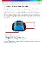
Page 5: ...port process The Transport Data Logger is designed according to the information provided in the data sheet Any use or operation which requires specific requirements and standards which aren t explicitly mentioned in the data sheet must be validated and tested on customer s own re sponsibility Figure 1 Overview TDL 1 Surface place your shipment code here 2 Button see chapter 5 Operation 3 LED green...

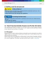
Page 6: ... normal operation is minimized 2 2 Disposal Disposing of this product correctly will help save valuable resources and prevent any potential negative effects on human health and the environment which could otherwise arise from inappropriate waste handling Please contact your local authority for further details of your nearest designated collection point Penalties may be applicable for incorrect dis...

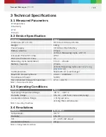
Page 7: ...emory Capacity 2 Years 15 min Measuring Cycle see Table 5 Log ging Intervals Communication Bluetooth 4 0 Low Energy Bluetooth Frequency Band 2 402 2 480 GHz Transmission Power 5 dBm Recommended Storage Temperature 0 C 40 C Table 1 Device Specifications 3 3 Operating Conditions Attribute Range Operating Temperature Range 25 C 80 C Humidity Range 0 rH 100 rH non condensing Acceleration Shock Range 8...

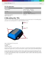
Page 8: ...ng purposes Figure 2 Mounting the TDL using screws 1 Screwdriver 2 Screw 3 Mounting holes In general the TDL can be mounted in any position as required The fastening depending on the specific requirements can be carried out with screws or with double sided adhesive tape In case shock shall be measured a direct and non absorbing connection between the TDL and the monitored good is required For achi...

Page 9: ... 5 1 Connecting to the TDL 3 Start the Transport Data Logger app 4 To find the activated TDL tap Search 5 Locate and select the TDL from the list 6 Confirm the connection by selecting Pair 1 Activate Bluetooth LE on your smartphone For devices running Android 6 enable GPS as well 2 To activate the TDL press the button on the device for 0 3 to 1 5 seconds INFO To enable Bluetooth LE Android 6 requi...

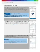
Page 10: ... TDL As an aid for configuration refer to the overview of the recommended configura tion intervals in 5 2 1 Logging Interval 5 Choose a measurement parameter temperature humidity tilt shock by tapping Set values 6 Swipe up and down to configure minimum and maximum values 7 Tap Continue Convention for Characters Only defined characters are allowed for the e mail address and TDL name Allowed charact...

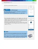
Page 11: ...L blinks green three times to confirm that logging has started No TDL Access You cannot configure the TDL without a valid PIN It is impossible to reset the PIN even at the factory Always make a note of the PIN and store it in a safe place Notice INFO The measurement starts immediately after you tap on Start logging The TDL uses its current position as a reference for the tilt measure ment If you c...

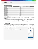
Page 12: ...e monitoring period the stored data can be analyzed and then cleared The measurement can be started from scratch again For logging intervals that are longer than 15 minutes the battery with a lifetime of 24 months will be the limiting factor 5 3 Settings You can change the settings of your TDL at any time Any change to the settings is protected by the PIN To change settings please connect to the r...

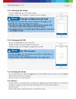
Page 13: ... Do you want to continue appears After the reset the device will be in the delivery state 2 Tap Reset 3 The LED blinks red three times to confirm the reset Storage of Measurement Data The log files are associated with a specific shipment Data logging can be interrupted upon request by tapping Stop logging The data recording will continue and data will be stored in the same file as long as the sett...

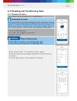
Page 14: ...detailed information Overview Screen This screen provides an overview of the four parameters showing you at a glance if any violations have occurred during the logging period Green check marks indi cate that no violation has occurred whereas an exclamation mark indicates that the limit values have been exceeded at least once during the logging period If an icon is shown grayed out no limit value h...

Page 15: ...and duration of the transport Configured limit values for all parameters Minimum and maximum values that were measured during the transport A graphical transport summary The CSV file that contains all the raw data and additional information such as the shock intensity to help analyze the shock event E Mail Account Required The report will be sent from the e mail account on your smartphone Ensure t...

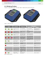
Page 16: ...3 times red 10 Hz Configuration trans mission or change setup has failed Transfer a configuration or changed setup to the TDL Possible reasons Vibra tions or a bad Bluetooth connectivity Blinks reiteratively green 0 2 Hz Bluetooth is enabled either connection or advertising Push the button for 0 3 to 1 5 s Lights up green for 3 s No violation has been registered Push the button for 0 3 to 1 5 s Li...

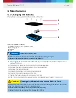
Page 17: ...CR 123A Lithium Battery 6 Position the mounting plate on the TDL 7 Fasten the four screws with a torque of 0 5 Nm 8 The TDL is now ready for use and can be configured see chapter 5 Operation 1 2 3 4 Figure 14 Changing the battery Risk of Data Loss No data can be measured or stored while the battery is being changed Always stop logging before removing the battery Notice Damage to Materials can caus...

Page 18: ...age to Materials can cause Risk of Fire Liquid which enters the device can cause short circuits and damage the device This could cause fire data loss and incorrect measurements Do not use aerosol sprays solvents or abrasives Do not spray cleaners directly onto the item Do not allow moisture to enter into any openings Caution ...

Page 19: ...on is subject to the following two conditions 1 This device may not cause harmful interference and 2 This device must accept any interference received including interference that may cause undesired operation The manufacturer is not responsible for any changes or modifications not expressly ap proved by the party responsible for compliance Such modifications may void the FCC authorization to opera...

Page 20: ...y Canada license exempt RSS standard s Operation is sub ject to the following two conditions 1 this device may not cause harmful interference and 2 this device must accept any interference including interference that may cause unde sired operation This Class B digital apparatus complies with Canadian ICES 003 7 5 Export Restrictions Due to legal regulations the device is not available in the follo...

Page 21: ...Bosch Connected Devices and Solutions GmbH Ludwig Erhard Straße 2 72760 Reutlingen Germany www bosch connectivity com ...

Reviews: