background image

2

en | Safety

UML-19P-90 LCD Monitor

F01U099396 | 1.0 | 2008.11

User’s Manual

Bosch Security Systems, Inc.

11.

Power sources - 

Operate the unit only from the type of power source indicated on the 

label. Before proceeding, be sure to disconnect the power from the cable to be installed 
into the unit.

For battery powered units, refer to the operating instructions.

For external power supplied units, use only the recommended or approved power 
supplies.

For limited power source units, this power source must comply with 

EN60950

Substitutions may damage the unit or cause fire or shock.

For 24 VAC units, voltage applied to the unit's power input should not exceed ±10%, 
or 28 VAC. User-supplied wiring must comply with local electrical codes (Class 2 
power levels). Do not ground the supply at the terminals or at the unit's power 
supply terminals.

If unsure of the type of power supply to use, contact your dealer or local power 
company.

12.

Servicing -

 Do not attempt to service this unit yourself. Opening or removing covers may 

expose you to dangerous voltage or other hazards. Refer all servicing to qualified service 
personnel.

13.

Damage requiring service -

 Unplug the unit from the main AC power source and refer 

servicing to qualified service personnel when any damage to the equipment has occurred, 
such as:

the power supply cord or plug is damaged;

exposure to moisture, water, and/or inclement weather (rain, snow, etc.);

liquid has been spilled in or on the equipment;

an object has fallen into the unit;

unit has been dropped or the unit cabinet is damaged;

unit exhibits a distinct change in performance;

unit does not operate normally when the user correctly follows the operating 
instructions.

14.

Replacement parts - 

Be sure the service technician uses replacement parts specified by 

the manufacturer, or that have the same characteristics as the original parts. 
Unauthorized substitutions may cause fire, electrical shock, or other hazards.

15.

Safety check -

 Safety checks should be performed upon completion of service or repairs 

to the unit to ensure proper operating condition.

16.

Installation - 

Install in accordance with the manufacturer's instructions and in 

accordance with applicable local codes.

17.

Attachments, changes or modifications - 

Only use attachments/accessories specified by 

the manufacturer. Any change or modification of the equipment, not expressly approved 
by Bosch, could void the warranty or, in the case of an authorization agreement, authority 
to operate the equipment.

1.2

Safety Precautions

DANGER! 

High risk:

This symbol indicates an imminently hazardous situation such as “Dangerous Voltage” 
inside the product. If not avoided, this will result in an electrical shock, serious bodily 
injury, or death.

Summary of Contents for UML-19P-90

Page 1: ...19 inch LCD Flat Panel Monitor UML 19P 90 en User s Manual ...

Page 2: ...ing the Monitor 11 5 1 Ventilation 11 5 2 Mounting the Monitor 11 5 2 1 Desktop Installation 11 5 2 2 Wall Mount Installation 11 5 2 3 Rack mount Installation 12 5 3 Connecting the PC Signal to the Monitor 14 6 Navigating the Monitor 14 6 1 Navigating the Front Panel 14 6 2 Navigating the Monitor On screen Display OSD 15 6 3 On screen Display Menus 15 6 4 Auto Adjust 16 6 5 Screen 17 6 6 RGB 18 6 ...

Page 3: ...iv en Table of Contents UML 19P 90 LCD Monitor F01U099396 1 0 2008 11 User s Manual Bosch Security Systems Inc ...

Page 4: ...of any kind into this unit through openings as they may touch dangerous voltage points or short out parts that could result in a fire or electrical shock Never spill liquid of any kind on the unit Do not place objects filled with liquids such as vases or cups on the unit 6 Lightning For added protection during a lightning storm or when leaving this unit unattended and unused for long periods unplu...

Page 5: ...damage to the equipment has occurred such as the power supply cord or plug is damaged exposure to moisture water and or inclement weather rain snow etc liquid has been spilled in or on the equipment an object has fallen into the unit unit has been dropped or the unit cabinet is damaged unit exhibits a distinct change in performance unit does not operate normally when the user correctly follows the...

Page 6: ...ns assembly must be within the environmental specification of 10 C 14 F to 50 C 122 F Camera signal Protect the cable with a primary protector if the camera signal is beyond 140 feet in accordance with NEC800 CEC Section 60 Coax grounding Ground the cable system if connecting an outside cable system to the unit Connect outdoor equipment to the unit s inputs only after this unit has had its groundi...

Page 7: ...not defeat the safety purpose of the polarized plug Alternately this unit may be equipped with a 3 pole grounding plug a plug with a third pin for earth grounding This safety feature allows the plug to fit into a grounded power outlet only If unable to insert the plug into the outlet contact a locally certified electrician to replace the obsolete outlet Do not defeat the safety purpose of the grou...

Page 8: ... the user s authority to operate the equipment If necessary the user should consult the dealer or an experienced radio television technician for corrective action The user may find the following booklet prepared by the Federal Communications Commission helpful How to Identify and Resolve Radio TV Interference Problems This booklet is available from the U S Government Printing Office Washington DC ...

Page 9: ... WARRANTIES OR CERTIFICATIONS WHATSOEVER REGARDING THE PERFORMANCE OR RELIABILITY OF ANY SECURITY OR SIGNALING RELATED FUNCTIONS OF THIS PRODUCT Disclaimer Underwriter Laboratories Inc UL has not tested the performance or reliability of the security or signaling aspects of this product UL has only tested fire shock and or casualty hazards as outlined in UL s Standard s for Safety for Information T...

Page 10: ...rt Telephone 800 326 1450 Fax 585 223 3508 or 717 735 6560 E mail technical support us bosch com Canada Telephone 514 738 2434 Fax 514 738 8480 Europe Middle East Africa Region Repair Center Telephone 31 0 76 5721500 Fax 31 0 76 5721413 E mail RMADesk STService nl bosch com Asia Region Repair Center Telephone 65 63522776 Fax 65 63521776 E mail rmahelpdesk sg bosch com Customer Service Telephone 86...

Page 11: ...8 en Safety UML 19P 90 LCD Monitor F01U099396 1 0 2008 11 User s Manual Bosch Security Systems Inc ...

Page 12: ...re use 2 1 Parts List The following table lists the parts included 3 Exploded View Figure 3 1 Front Panel Quantity Part 1 UML 19P 90 Color LCD Flat Panel Monitor 1 User s manual 2 Power Cords 3 wire with grounded plug 1 8 m 6 ft long one with a U S plug type and one with a European Continental plug type 1 VGA to VGA D SUB cable 1 5 m 5 ft 1 Power Supply brick UML 19P 90 12 VDC 4 16 A 100 240 VAC 5...

Page 13: ...and DVI signals 19 inch 100 240 VAC Power Supply High resolution Display 1280 x 1024 VGA Input DVI D Input On screen Display OSD with Multiple Languages 4 Adjusts the value when in the OSD or decreases Audio Mute menu Scrolls down in the OSD 5 Decreases the value when in the OSD or decreases the volume Scrolls left in the OSD 6 Increases the value when in the OSD or increases the volume Scrolls ri...

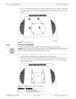
Page 14: ...ith a 3 pole US style power cord and a 2 pole Euro style power cord Use the US style power cord where 120 VAC 60 Hz power is available use the Euro style power cord where 230 VAC 50 Hz power is available The monitor automatically adjusts to either power input voltage 5 2 2 Wall Mount Installation The square mounting holes 100 mm 3 9 in centers are compatible with the Bosch UMM LW 20B fixed wall mo...

Page 15: ...using the RMK 08 mounting bracket do the following 1 Use a Phillips head screw driver to remove the base of the monitor 2 Align the two 2 supplied mounting guide brackets flush with the screw holes on the back of the monitor Screw the 4 supplied self tapping screws into the non threaded holes see Figure 5 3 Figure 5 3 RMK 08 Mounting Guide Bracket Installation i NOTICE Prior to installing the UML ...

Page 16: ...ts from the 8C or current position and screw to the 9V position 4 Adjust the location of the inner brackets so they align flush with the inner threaded holes on the back of the monitor 5 Secure the RMK 08 rack mount bracket to the UML 19P 90 flat panel from the back side using the VESA 100 mm mounting points and the supplied four 4 M4 8 Phillips screws ...

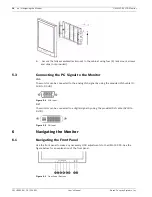
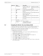
Page 17: ... VGA The monitor can be connected to the analog VGA signal by using the provided VGA cable D SUB to D SUB Figure 5 4 VGA Input DVI The monitor can be connected to a digital signal by using the provided DVI cable DVI D to DVI D Figure 5 5 DVI Input 6 Navigating the Monitor 6 1 Navigating the Front Panel Use the front panel to make any necessary OSD adjustments to the UML 19P 90 See the figure below...

Page 18: ... 1 4 Press the Menu button to activate the main menu selections see Figure 3 1 5 Press the and the buttons to select a main menu 6 Press the Input button to enter a selected menu 7 Press the and the button to toggle the OSD values 8 When finished scroll to Exit and press the Menu button Note If there is no Exit option press the Menu button Reference Button Description 1 Input Button Selects the si...

Page 19: ... information about the current graphics adapter settings Icon Menu Function Auto Adjust Adjusts the screen size when input is in DSUB Analog VGA mode Screen Adjusts the Brightness and Contrast in both modes H Position V Position Phase Adjust and Clock Adjust performance in VGA mode RGB Selects User 9300 6500 Adjusts the Color Temp of the monitor MIN 1 99 MAX Utility Enables the user to reset all s...

Page 20: ... Screen submenu options DVI Digital Mode DSUB Analog VGA Mode BRIGHTNESS CONTRAST H POSITION V POSITION PHASE ADJUST CLOCK ADJUST 1280x1024 63 9 kHz 60Hz BRIGHTNESS CONTRAST H POSITION V POSITION PHASE ADJUST CLOCK ADJUST 1280x1024 63 9 kHz 60Hz Submenu Definition BRIGHTNESS Adjusts the brightness level for video performance range MIN 1 99 MAX CONTRAST Adjusts the contrast level for video performa...

Page 21: ...usts the vertical position for the desktop range MIN 1 99 MAX Note not available in DVI Digital mode PHASE ADJUST Adjusts for best picture quality by adjusting for sharpness of vertical lines range MIN 1 99 MAX Note not available in DVI Digital mode CLOCK ADJUST Adjusts the best picture quality by adjusting the horizontal size of the video displayed range MIN 1 99 MAX Note not available in DVI Dig...

Page 22: ...e English French German Spanish and Korean To access the Language submenu press the Menu button on the front panel of the monitor press the Input button then press the left and right arrows to select the Language icon Press the up and down arrows to select the Language submenu options DVI Digital and DSUB Analog VGA Modes RECALL FULL AUTO INPUT SELECT 1280x1024 63 9 kHz 60Hz Submenu Definition REC...

Page 23: ...itor press the Input button then press the left and right arrows to select the Audio icon Press the up and down arrows to select the Audio submenu options DVI Digital and DSUB Analog VGA Modes OSD TIME OUT OSD H POSITION OSD V POSITION OSD TRANSPARENCY 1280x1024 63 9 kHz 60Hz Submenu Definition OSD TIME OUT Adjusts the on screen display time range 5s 60s OSD H POSITION Adjusts the horizontal posit...

Page 24: ...ature of the monitor is comprised of three stages On green Unsupported mode green and Standby Power Off red 8 Trouble Shooting Guide Submenu Definition AUDIO VOLUME Adjusts the audio volume range MIN 1 99 MAX AUDIO MUTE Enables or disables the mute function options ON and OFF Mode UML 19P 90 ON 40 W STANDBY 3 0 W Problem Solution No image is displayed on screen Check that the power cord of the mon...

Page 25: ...ollowing as a cleaning agent Ketone type materials Ethyl alcohol Ethyl acid Tolulene Methyl chloride Ammonia Use of these materials may permanently damage the polarizer due to a chemical reaction Vertical or horizontal noise is present in the picture in VGA mode Adjust the Clock and Phase in the Screen submenu Incorrect colors Press the Menu button on the front panel of the monitor then press the ...

Page 26: ......

Page 27: ......
Page 28: ...h Security Systems B V P O Box 80002 5600 JB Eindhoven The Netherlands Phone 31 40 2577 284 Fax 31 40 2577 330 emea securitysystems bosch com www boschsecurity com Asia Pacific Bosch Security Systems Pte Ltd 38C Jalan Pemimpin Singapore 577180 Phone 65 6319 3450 Fax 65 6319 3499 apr securitysystems bosch com www boschsecurity com Bosch Security Systems 2008 F01U099396 1 0 2008 11 Data subject to c...

Reviews: