4
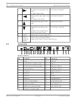
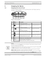
Increases the value when in the
OSD.
Increases audio volume.
Scrolls right in the OSD.
5
Decreases the value when in the
OSD.
Decreases audio volume.
Scrolls left in the OSD.
6
Adjusts the value when in the
OSD.
Scrolls up in the OSD.
7
Adjusts the value when in the
OSD.
Activates the Auto Adjustment
function when in PC mode.
Scrolls down in the OSD.
8
MENU
Selects the on-screen display (OSD).
9
VIDEO
SOURCE/
ENTER
Selects the signal to be displayed.
Serves as the “Enter” function for OSD menus.
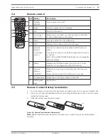
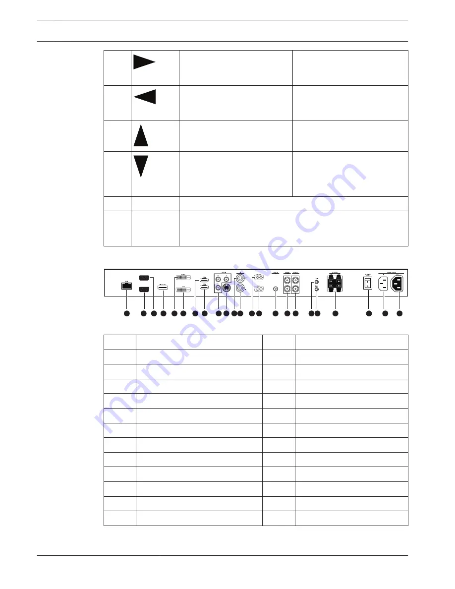
Connectors
RS-232C-OUT
RS-232C-IN
1
4
3
12
13 14
15
16
18 19
20
21
22
23
2
5
6
10 11
9
7
8
17
Figure 3.5: Connectors
Ref.
Connector
Ref.
Connector
1
RJ-45
13
VGA OUT
2
RS-232 IN (for firmware update)
14
VGA IN
3
RS-232 OUT (for firmware update
15
AUDIO IN - AUDIO 2
4
DISPLAY PORT IN
16
AUDIO IN - AUDIO 3
5
DVI-D OUT
17
AUDIO OUT (R/L)
6
DVI-D IN
18
IR IN
7
HDMI IN 2
19
IR OUT
8
HDMI IN 1
20
SPEAKERS (R/L)
9
VIDEO IN (COMPONENT)
21
AC SWITCH ON/OFF
10
VIDEO IN (S-VIDEO)
22
100 - 240 VAC IN
11
VIDEO OUT (Composite, BNC)
23
100 - 240 VAC OUT
12
VIDEO IN (Composite, BNC)
3.3
14
en | Access and connections
High Performance HD LED Monitor
2013.07 | v1.0 | F.01U.286.147
User Manual
Bosch Security Systems
Summary of Contents for UML-463-90
Page 1: ...High Performance HD LED Monitor UML 463 90 en User Manual ...
Page 2: ......
Page 41: ......

