background image

Power

On/Off

Control Panel Lockout

Multiple push-button combination


On-screen Display

Video Mode

Input Source, Screen, OSD, Utility


Indicators (on rear)

LED

Power On (green)
Power Off, Standby (red)


Connectors

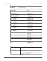
Video 1 (AV1)

Composite video: two (2) BNC (1 in, 1 out)

Digital

Two (2) (1 DVI-D in, 1 DVI-D out)

IR

Two (2) (1 in, 1 out)

Display port

One (1) in

HDMI

Two (2) in

VGA

One (1): 1 RGB 15-pin D-sub in, 1 RGB 15-pin D-sub out

Component

One (1): Y, Pb, Pr

Y/C (S-video)

One (1) mini-DIN, 4-pin (1 in)

Audio

1 Audio In: RCA (right/left)
1 Audio In: phono jack
1 Audio Out: RCA (right/left)
1 Speaker Out (right/left)

RS-232

Two (2) (1 in for firmware update, 1 out for firmware update)

Power Input

100 – 240 VAC

Power Output

100 – 240 VAC

 
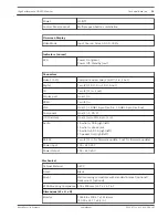
Mechanical

Cabinet Material

SECC

Finish

Black

Mount

Wall mounting compatible with standard bracket (optional)
Desk mount (optional)

VESA Mounting Compliance 400 x 400 mm (15.7 x 15.7 in.)

Dimensions (W x H x D)

Monitor

1023.68 x 578.27 x 111.8 mm
(40.30 x 22.77 x 4.4 in.)

High Performance HD LED Monitor

Technical data | en

39

Bosch Security Systems

User Manual

2013.07 | v1.0 | F.01U.286.147

Summary of Contents for UML-463-90

Page 1: ...High Performance HD LED Monitor UML 463 90 en User Manual ...

Page 2: ......

Page 3: ...the Monitor 18 5 5 Connecting the Y C S Video Signal to the Monitor 18 5 6 Connecting Audio to the Monitor 19 5 7 Connecting the PC Signal to the Monitor 19 5 7 1 VGA Connection 19 5 7 2 HDMI Connection 19 5 7 3 DVI Connection 20 5 7 4 DisplayPort 20 5 8 Single Multiple Monitor Configuration 20 5 9 Connecting to the network LAN 21 6 Navigating the Monitor 23 6 1 Navigating the Control Panel 23 6 2...

Page 4: ... place objects filled with liquids such as vases or cups on the unit 6 Lightning For added protection during a lightning storm or when leaving this unit unattended and unused for long periods unplug the unit from the wall outlet and disconnect the cable system This will prevent damage to the unit from lightning and power line surges 7 Controls adjustment Adjust only those controls specified in the...

Page 5: ... 15 Safety check Safety checks should be performed upon completion of service or repairs to the unit to ensure proper operating condition 16 Installation Install in accordance with the manufacturer s instructions and in accordance with applicable local codes 17 Attachments changes or modifications Only use attachments accessories specified by the manufacturer Any change or modification of the equi...

Page 6: ...ice pursuant to Part 15 of the FCC Rules and ICES 003 of Industry Canada These limits are designed to provide reasonable protection against harmful interference when the equipment is operated in a commercial environment This equipment generates uses and radiates radio frequency energy and if not installed and used in accordance with the instruction manual may cause harmful interference to radio co...

Page 7: ...rohibits surreptitious recording of oral communications Environmental statement Bosch has a strong commitment towards the environment This unit has been designed to respect the environment as much as possible Electrostatic sensitive device Use proper CMOS MOS FET handling precautions to avoid electrostatic discharge NOTE Wear required grounded wrist straps and observe proper ESD safety precautions...

Page 8: ... from Bosch Caution Connecting System ground to Safety ground may result in ground loops that can disrupt the CCTV system Video loss Video loss is inherent to digital video recording therefore Bosch Security Systems cannot be held liable for any damage that results from missing video information To minimize the risk of lost digital information Bosch Security Systems recommends multiple redundant r...

Page 9: ... that the content of the user guide can change without notice Bosch Security Systems accepts no liability for damage resulting directly or indirectly from faults incompleteness or discrepancies between the user guide and the product described Trademarks All hardware and software product names used in this document are likely to be registered trademarks and must be treated accordingly Customer supp...

Page 10: ...1710 E mail customer service cn bosch com Warranty and more information For additional information and warranty queries please contact your Bosch Security Systems representative or visit our website at www boschsecurity com 10 en Safety High Performance HD LED Monitor 2013 07 v1 0 F 01U 286 147 User Manual Bosch Security Systems ...

Page 11: ...and must be used if returning the unit for service Save it for possible future use Parts List Quantity Description 1 UML 463 90 Color LED Flat Panel Monitor 1 Installation manual printed booklet English version 1 Installation manual CD ROM multi language version 2 Power Cords 3 wire with grounded plug 1 8 m 6 ft long one with a U S plug type one with a European Continental plug type 1 DVI D to DVI...

Page 12: ...Figure 3 1 Front with dimensions 111 8 61 58 24 Figure 3 2 Side with dimensions 400 M6 x 4 PCS 539 441 2 440 Figure 3 3 Back with dimensions 3 3 1 12 en Access and connections High Performance HD LED Monitor 2013 07 v1 0 F 01U 286 147 User Manual Bosch Security Systems ...

Page 13: ...er is turned on Lights up red when display is turned off Lights up red when display is in Power Save High mode Flashes red when display is in Power Save Low mode Off when power is turned off 2 LED Indicator Indicates the operating status of the monitor Lights up green when power is turned on Lights up red when display is turned off Lights up red when display is in Power Save High mode Flashes red ...

Page 14: ... menus Connectors RS 232C OUT RS 232C IN 1 4 3 12 13 14 15 16 1819 20 21 22 23 2 5 6 10 11 9 7 8 17 Figure 3 5 Connectors Ref Connector Ref Connector 1 RJ 45 13 VGA OUT 2 RS 232 IN for firmware update 14 VGA IN 3 RS 232 OUT for firmware update 15 AUDIO IN AUDIO 2 4 DISPLAY PORT IN 16 AUDIO IN AUDIO 3 5 DVI D OUT 17 AUDIO OUT R L 6 DVI D IN 18 IR IN 7 HDMI IN 2 19 IR OUT 8 HDMI IN 1 20 SPEAKERS R L...

Page 15: ...ress to return to the Main menu from anywhere in the OSD menus 9 Numeric buttons 0 MUTE Performs as a numeric button when the OSD menu is active Mutes the sound when the OSD menu is inactive 10 Up down keys Moves the cursor up and down in the OSD 11 Multi media keys No function Remote Control Battery Installation 1 Turn the remote over buttons facing down and push down on the cover and slide it of...

Page 16: ... on a desktop You can access the monitor control functions from the push buttons and the on screen display OSD menus Refer to Access and connections page 12 for descriptions of the connectors and push buttons available on each model Feature overview Full HD 1920 x 1080 resolution Precise color reproduction HDMI DVI VGA S Video inputs Super slim bezel for seamless tiled wall mounting High contrast ...

Page 17: ...ystems Inc Web site or contact your local customer support representative for more information Wall mount installation The monitor can be wall mounted using the mounting holes and a suitable wall mount or swivel tilt mount Use UL Listed mounting standards and ensure the mounts are strong enough to bear the weight of the monitor Refer to the following figure for the dimensions of the wall mounting ...

Page 18: ...or There is one 1 BNC connector located on the rear panel of the monitor for composite video input and one 1 BNC connector for composite video output Refer to Connectors page 14 Note All video inputs are passive loop through The impedance is automatically set to 75 ohm by the input of the signal on the input connector while operating in a single connection mode refer to page 20 If a cable is also ...

Page 19: ...e monitor HDMI DVI VGA and DISPLAY PORT VGA Connection Connect the PC signal using the VGA connector on the rear panel and a VGA cable D SUB to D SUB Figure 5 4 VGA Input Pin Description Pin Description Pin Description 1 Red Video 6 Red Ground 11 Ground 2 Green Video 7 Green Ground 12 SDA for DDC 3 Blue Video 8 Blue Ground 13 H Sync or H V Sync 4 Ground 9 N A 14 V Sync 5 Ground 10 Signal Cable Det...

Page 20: ...nnector on the rear panel and a DP cable DP to DP Figure 5 7 DisplayPort IN Single Multiple Monitor Configuration 1 2 3 4 Figure 5 8 Single Monitor Configuration Ref Description Ref Description 1 Video Camera 3 Video Out 2 Video In 4 DVR 5 7 3 5 7 4 5 8 20 en Installing the Monitor High Performance HD LED Monitor 2013 07 v1 0 F 01U 286 147 User Manual Bosch Security Systems ...

Page 21: ...t mask Default gateway Primary DNS and Secondary DNS settings will be displayed 5 If you are not in a DHCP environment select Manual Execute and press ENTER Contact your IT administrator for information on the IP Address Subnet mask Default gateway Primary DNS and Secondary DNS settings and enter them accordingly 6 To save the settings and return to the previous menu select Execute then press ENTE...

Page 22: ...twork Provides options for manually setting the monitor IP address obtaining an IP address from a DHCP server setting changing the user name and password to secure this network control system Notes You cannot control the display via the RS 232C connector when LAN control is in use It is recommended that you use Internet Explorer versions 7 0 or higher If you need to turn on the display from a web ...

Page 23: ...VIDEO SOURCE ENTER Selects the signal to be displayed Serves as the Enter function for OSD menus Notice This monitor has a special key lock function for both the control panel and remote control to prevent unintentional operator actions Lock unlock the buttons on the control panel by simultaneously pressing and holding the left and right arrow buttons on the control panel for 5 seconds Lock unlock...

Page 24: ... or INPUT on the remote control and then the up and down arrow buttons until the correct signal is displayed Confirm your selection by pressing the VIDEO SOURCE ENTER button or the ENTER button on the remote control You can also directly choose the desired signal button on the remote control To navigate within the OSD menus follow the steps below 1 Press the MENU button to activate the main menu s...

Page 25: ... 27 Screen Adjust relevant screen display settings See Screen Menu page 28 Settings Resets the factory default settings and adjust the overall monitor settings See Setting Menu page 31 Note Some of the OSD menu functions may not be available depending on the input source detected Picture Menu Access the Picture menu using the MENU button on control panel or remote control Figure 6 2 Picture menu 6...

Page 26: ...the overall color intensity of the screen range 0 100 Phase Adjusts the phase of the picture range 0 100 Sharpness Adjusts the sharpness level for video performance range 0 100 Color Temp Selects the color temperature Choices are 11000 K 9300 K 6500 K Custom options here are Red Green and Blue Noise reduction Reduces electrical image noise caused by different media players Film mode Optimizes the ...

Page 27: ...de on or off Speaker Sets the audio output source Line Out Selects the audio output source from AUDIO OUT R L on connector panel External Selects the audio output source from SPEAKERS R L on connector panel Internal Select the audio output source from the internal speakers Audio Source Selects the audio input source Audio1 connector Audio2 connector HDMI1 connector HDMI2 connector DisplayPort conn...

Page 28: ...inations See PAP Availability page 30 for more information on supported combinations In PAP mode only sound from the active picture will be available Display wall H Monitors V Monitors Sets the number of displays used in the horizontal vertical direction H Position V Position Sets the horizontal vertical position of the display wall matrix Frame Comp Adjusts images near the display edges for optim...

Page 29: ...it displays in the same 16 9 aspect ratio 4 3 Displays all picture sources in 4 3 aspect ratio Full 1 Enlarges the picture to fill the screen in the vertical direction keeping the same aspect ratio A black frame may appear around the picture Full 2 Enlarges the picture to fill the screen Real Displays the picture in its original number of dots For video signal inputs For PC signal input High Perfo...

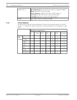
Page 30: ...n to freeze the displayed image PAP Availability The table below summarizes the availability of the input source combinations for the PIP feature indicates accepted combination a blank cell indicates the combination is not valid Main Picture Input Source AV S Video YPbPr VGA DVI HDMI DisplayPor t Sub Picture AV S Video YPbPr VGA DVI HDMI DisplayPort 6 6 1 30 en Navigating the Monitor High Performa...

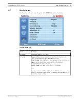
Page 31: ...Clock Display Sets whether to show the current time which was set Input Sets an input source to display when the display is automatically turned on next time On Off Timer Sets when to turn on or off the display Note Set the current time before setting the On Off Timer When scheduling settings overlap the Everyday setting takes priority over other weekly settings 6 7 High Performance HD LED Monitor...

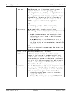
Page 32: ...eceive the control signal from the primary display via the RS 232 connection Note To reset to the default setting RS 232C press INFO on the remote control for 5 seconds Network Settings See Connecting to the network LAN page 21 Set Monitor ID Sets the ID number for controlling the monitor when multiple monitors are connected under the RS 232C control mode Each monitor must have a unique ID number ...

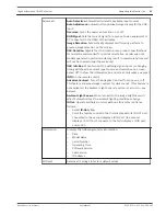
Page 33: ...n box on screen only when you press INFO on the remote control Adaptive Contrast Turns the Adaptive Contrast function on or off This feature enhances image contrast for dark scenes This feature is not available if the Ambient Light Sensor function is set to On see below Ambient Light Sensor When turned On the image brightness will adjust automatically as the ambient lighting conditions change IR O...

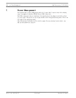
Page 34: ...aling by not sending a horizontal vertical or a sync signal The monitor enters an appropriate mode through identifying each of the three 3 modes of the signaling system The LED indicator on the back of the monitor signals the current power mode status see Rear panel exploded view page 13 7 34 en Power Management High Performance HD LED Monitor 2013 07 v1 0 F 01U 286 147 User Manual Bosch Security ...

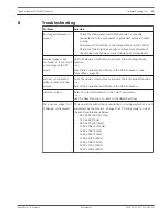
Page 35: ...l or horizontal noise is present in the picture Push the down arrow button to activate the Auto Adjust function or Adjust the Frequency and Phase in the OSD submenu Incorrect colors Select a color temperature in the Color Temp menu or Use the Reset function to reset to the default settings The error message Out of Range is displayed PC is operating with either a resolution or timing mode that is n...

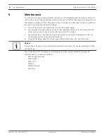
Page 36: ...ater only a paper towel or dirty cloth can scratch the screen 3 Gently wipe the screen starting from top to bottom wiping in a downward motion Do not damage the screen by pressing too hard 4 To avoid streaking wipe the screen again with another clean dry lint free cloth Notice If water does not work use a mild cleaner labeled for use with LCD panels available at office supply stores Do not use any...

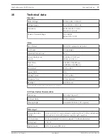
Page 37: ...s 1073 7 million Response Time 6 5 ms typical Backlight 50 000 hours 1 Pixel Policy Bosch monitors follow the ISO 13406 2 Class II standard LCD Panel Optical Characteristics Luminance 450 cd m2 typical Contrast Ratio 3500 1 typical Viewing Angle Horizontal Vertical 178 typical Video Input Composite Video CVBS 1 0 Vp p 0 5 1 5 Vp p automatic switching from 75 Ohm unbalanced termination to Hi Z with...

Page 38: ...z 1400 x 1050 60 Hz 1400 x 1050 60 Hz 1600 x 1200 60 Hz 1600 x 1200 60 Hz 1680 x 1050 60 Hz 1680 x 1050 60 Hz 1920 x 1080 60 Hz 1920 x 1080 60 Hz 480i 60 Hz 480p 60 Hz 576i 50 Hz 576p 50 Hz 720p 25 3050 60 Hz 1080i 50 60 Hz 1080p 24 25 30 50 60 Hz 1080p 24 25 Psf Controls Input Rear Control Panel Push buttons Remote control Push buttons Video Source Selects Component Video S video VGA HDMI DVI D M...

Page 39: ... video One 1 mini DIN 4 pin 1 in Audio 1 Audio In RCA right left 1 Audio In phono jack 1 Audio Out RCA right left 1 Speaker Out right left RS 232 Two 2 1 in for firmware update 1 out for firmware update Power Input 100 240 VAC Power Output 100 240 VAC Mechanical Cabinet Material SECC Finish Black Mount Wall mounting compatible with standard bracket optional Desk mount optional VESA Mounting Compli...

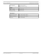
Page 40: ... 55 12 lb Shipping Weight 30 kg 66 14 lb Environmental Operating Temperature 0 C to 50 C 32 F to 122 F Storage Temperature 0 C to 50 C 32 F to 122 F Humidity 0 to 90 Relative 40 en Technical data High Performance HD LED Monitor 2013 07 v1 0 F 01U 286 147 User Manual Bosch Security Systems ...

Page 41: ......

Page 42: ...Bosch Security Systems B V Torenallee 49 5617 BA Eindhoven The Netherlands www boschsecurity com Bosch Security Systems B V 2013 ...

Reviews: