UMS Series Public View System
Troubleshooting | en
21
Bosch Security Systems, Inc.
Installation Manual
F01U029703 | 1.0 | 2006.07
9
Troubleshooting
The following are commonly asked troubleshooting questions to better assist you in operating
your UMS monitor.
9.1
Make adjustments to the control board and option switches
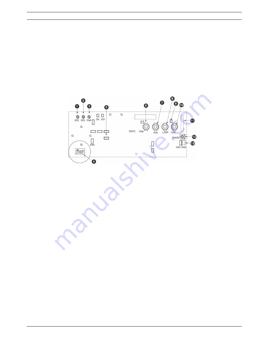
The control board is a microprocessor-based circuit that controls the on-board sensors and a
two (2) channel video switcher. The main purpose of the switcher is to display the image from
the on-board camera when the PIR detects motion. It may also be directed to ignore the sen-
sor and select one of the two (2) video signals.
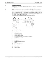
The following figure details the control board and the option switches:
Fig. 9.1
Control Board Configuration
.
Ref. # Description
1
Camera ON LED (red)
2
System Pulse LED (red)
3
System Power LED (green)
4
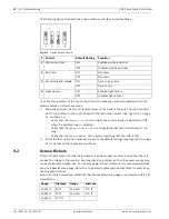
Option Switches (see
Figure 9.2
on page 22 for details)
5
RS-232 (factory use only)
6
LCD Monitor Video
7
Aux Video In
8
Internal Camera Video Out Loop
9
Video In
10
Reserved for future use
11
Power Connector
12
Phase Control
13
Power to Camera


