background image

 en

vii

F01U029703 | 1.0 | 2006.07

Bosch Security Systems, Inc.

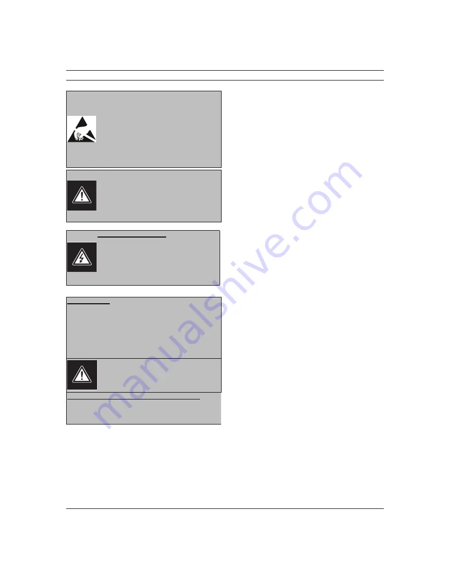
AVERTISSEMENT:
cet appareil est sensible aux décharges électrosta-
tiques. Pour éviter tout risque de décharge élec-
trostatique, observez les précautions de 
manipulation du CMOS/MOSFET appropriées.
REMARQUE : lors de la manipulation des cartes à 
circuits imprimés sensibles aux décharges élec-
trostatiques, portez des bracelets antistatiques 
mis à la terre et observez les consignes de sécu-
rité relatives aux décharges électrostatiques.

ATTENTION : pile au lithium 
Le remplacement incorrect de la pile risque de 
provoquer une explosion. Remplacez la pile exclu-
sivement par une pile identique ou par un type de 
pile équivalent recommandé par le fabricant. 
Débarrassez-vous de la pile usagée conformément 
aux instructions de son fabricant.

Enlèvement du capot

Avertissement : L’enlèvement du capot ne doit 
être effectué que par un technicien spécialisé. Il 
n’y a pas de pièces remplaçables ou réglables par 
l’utilisateur. Il faut toujours débrancher l’appareil 
avant d’enlever le capot et le laisser débranché 
jusqu’à la remise en place du capot.

24 VAC Units

Ne pas excéder 30 V c.a. La tension appliquée à l’entrée d’ali-
mentation de l’appareil ne doit pas excéder 30 V c.a. La valeur 
normale de la tension d’entrée est 24 V c.a. Le circuit élec-
trique reliant l’alimentation 24 V c.a. à l’appareil doit être con-
forme aux codes électriques (niveaux d’alimentation de classe 
2). Ne pas mettre l’alimentation 24 V c.a. à la masse au niveau 
des bornes de l’alimentation ou de l’appareil.

Cet équipement doit être isolé de l’alimentation 
secteur par une source de puissance limitée, con-
formément à la norme EN60950.

Cordons d’alimentation 220-240 V, 50 Hz

Les cordons d’alimentation 220-240 V, 50 Hz, d’entrée ou de 
sortie, doivent être conformes à la dernière version de la publi-
cation IEC 227 ou IEC 245.

Summary of Contents for UMS-20 Series

Page 1: ...UMS Series Public View Monitor UMS 20xxxA and UMS 20xxxC en Installation Manual ...

Page 2: ...r other hazards 9 Safety Check Upon completion of servicing or repairs to the unit ask the service technician to perform safety checks to ensure proper operating condition 10 Power Sources Operate the unit only from the type of power source indicated on the label If unsure of the type of power supply to use contact your dealer or local power company For units intended to operate from battery power...

Page 3: ...ATV systems For Rack mount Product 1 Ventilation Do not place this equipment in a built in installation or rack unless proper ventilation is pro vided or the manufacturer s instructions were followed The equipment must not exceed its maximum operating temperature requirements 2 Mechanical Loading When rack mounting the equip ment ensure that a hazardous condition is not created by uneven mechanica...

Page 4: ...ty to operate the equipment If neces sary the user should consult the dealer or an experienced radio television technician for corrective action The user may find the following booklet prepared by the Federal Communi cations Commission helpful How to Identify and Resolve Radio TV Interference Problems This booklet is available from the U S Government Printing Office Washington DC 20402 Stock No 00...

Page 5: ...C peut s avérer utile How to Identify and Resolve Radio TV Interfer ence Problems Comment identifier et résoudre les problèmes d interférences de radio et de télévision Cette brochure est disponible auprès du U S Government Printing Office Washington DC 20402 États Unis sous la référence n 004 000 00345 4 Sécurité Attention l installation doit exclusivement être réalisée par du Avertissement Ce pr...

Page 6: ...nt L enlèvement du capot ne doit être effectué que par un technicien spécialisé Il n y a pas de pièces remplaçables ou réglables par l utilisateur Il faut toujours débrancher l appareil avant d enlever le capot et le laisser débranché jusqu à la remise en place du capot 24 VAC Units Ne pas excéder 30 V c a La tension appliquée à l entrée d ali mentation de l appareil ne doit pas excéder 30 V c a L...

Page 7: ...viii en Bosch Security Systems Inc F01U029703 1 0 2006 07 ...

Page 8: ...v repair us bosch com CCTV Spare Parts Phone 800 894 5215 or 408 957 3065 Fax 408 935 5938 Email BoschCCTVparts ca slr com Canada Phone 514 738 2434 Fax 514 738 8480 Europe Middle East Asia Pacific Region Phone 44 0 1495 274558 Fax 44 0 1495 274280 Email rmahelpdesk solectron com For additional information see www boschsecurity com Related Publications Refer to the latest Bosch Security Systems Da...

Page 9: ...x en UMS Series F01U029703 1 0 2006 07 Installation Manual Bosch Security Systems Inc ...

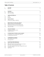
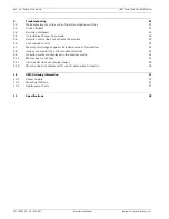
Page 10: ...splay OSD 7 4 3 Monitor Remote Control On screen Display Menus 7 4 4 Input Select Menu 9 5 Using the Card Reader 10 5 1 Compatible Flash Memory Cards 10 5 2 Image Requirements 10 6 Card Reader Remote Control Functions SanDisk 12 6 1 Card Reader On screen Display Menu Selections 12 6 2 Card Reader Menu Selections 13 7 Configuring Motion Detection 16 7 1 Selecting a Mounting Location 16 7 2 Activati...

Page 11: ...e control does not activate the monitor 24 9 6 Lost remote control 24 9 7 Memory card images appear stretched and out of proportion 25 9 8 Images are smaller than the recommended size 25 9 9 Question marks are displayed in the preview mode 25 9 10 Movie clips do not play 25 9 11 Card reader does not display images 25 9 12 Monitor does not display AUTO or AUX video when turned on 26 10 UMS Ordering...

Page 12: ...iner in which to transport the unit Save it for possible future use 1 1 Parts List The following table lists the components that comes with all UMS Series systems The following additional equipment comes with the UMS 20xxxC Series models Qty Item 1 UMS LCD monitor 1 Monitor remote control Bosch with two 2 AAA batteries 2 Wago clamps used to connect the power leads from the UMS Public View Monitor ...

Page 13: ... auto iris lens has 640 x 480 pixels resolution includes four 4 memory card reader slots features advanced power management and supports plug and play technology 2 2 UMS Series Models Each UMS Series Public View system offers some or all of the following features 20 1 inch LCD flat panel monitor High resolution color and wide dynamic range camera options Integrated memory card reader for storing w...

Page 14: ... provided with the UMS Series In addition the UMS Series features two mounting holes in which you can attach a sign to the UMS Series housing The following illustration details the mounting hole patterns on the back of the UMS monitor Fig 3 1 UMS Series Mounting Hole Pattern CAUTION Installation should be performed by qualified service installers only using construction methods in accordance with ...

Page 15: ... on 3 4 Video Connections Each UMS Series model offers either a Video In or a Video Out connector 3 4 1 Video In UMS 20xxxA models only If you have an external video source you would like to use as the auxiliary source connect the cable to the Video In connector 3 4 2 Video Out both models To connect the camera to a monitoring station attach a coax cable to the Video Out connec tor on the unit to ...

Page 16: ...tion 1 Turn the remote over buttons facing down and push down on the cover and slide it off 2 Insert two 2 new AAA alkaline batteries matching the batteries to the and marks inside the battery case Fig 3 2 Battery Installation 3 Slide the battery cover back into place i NOTICE Replace batteries when required or at least once a year Dispose of used batteries properly ...

Page 17: ...en Display OSD menu for the LCD panel CAM Displays ONLY video from the internal CCTV camera disables switching from CCTV video to auxiliary video Moves the cursor up in an OSD menu AUX Displays ONLY a JPG image or video from an external source depending on the model number disables switching from auxiliary video to the internal CCTV camera Moves the cursor left or decreases item values in an OSD m...

Page 18: ...the steps below 1 Power on the unit by aiming the Bosch remote control at the bottom portion of UMS and press the ON button 2 Press the MENU button to activate the Main menu selections Video OSD On screen Display Misc Input Select 3 Press the and buttons to select a main menu 4 Press the and buttons to navigate through the sub menus 5 Press the and buttons to select and edit any of the sub menus 6...

Page 19: ...ation of time 0 60 seconds that the unit displays the OSD and gives you the option to switch Languages Fig 4 2 OSD Menu Example Table 4 3 Submenu Default Settings Submenu Default Setting Definition Sharpness 0 Adjusts the clarity Brightness 50 Adjusts the background black level Backlight 75 Adjusts the luminance level Contrast 50 Adjusts the foreground white level Color 50 Adjusts the saturation T...

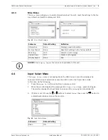
Page 20: ...o the following 1 Press the Power On button on the Bosch remote control 2 When the monitor displays the message DPMS Power Save Mode press MENU again The monitor displays the Input Select screen and the Video option should be ON 3 If Video is not ON use the or buttons to select Video then press the button to automatically display video on the monitor Fig 4 4 Input Select Menu Submenu Default Setti...

Page 21: ...Card SD MMC SanDisk recommended Compact FlashTM CF SanDisk recommended Sony Memory StickTM MS 5 2 Image Requirements Your memory card must contain a baseline JPEG image with a recommended size of 640 x 480 pixels in its root directory A baseline JPEG is stored as one top to bottom scan of the image If this size is not met the image may appear out of proportion Use of a TIFF or other incorrect form...

Page 22: ...2 Press the AUX button to display the JPEG image s If more than one JPEG is on the card the UMS displays a slide show rotating through all supplied JPEG images 5 2 3 Removing the Flash Memory Card To remove your flash memory card pull the card out Ref Description 1 Sony Memory StickTM input slot 2 Compact FlashTM CF input slot 3 Secure Digital MultiMedia Card SD MMC input slot 4 Smart MediaTM SM i...

Page 23: ...age 11 for details 3 Use the memory card remote control SanDisk to activate the main menu selections Press the PAUSE button followed by the MENU SELECT button The unit displays the fol lowing menus Select Memory Card Display Photo Info Slide Show Delay TV Screen Display Picture Position Language Exit Button Function PLAY SLIDE SHOW Plays images continuously from your memory card PAUSE Pauses the s...

Page 24: ... settings 6 2 1 Select Memory Card Menu The Select Memory Card menu allows you to choose the memory card you would like to access Fig 6 1 Memory Card Menu 6 2 2 Display Photo Info Menu The Display Photo Info menu allows you to display the image information date time size of file and resolution Fig 6 2 Photo Info Menu i NOTICE The effects called Transition Effects that the card reader displays betw...

Page 25: ...splay menu allows you to display images in either Full Screen mode or in the true image size The true image setting is best if your images are 640 x 480 pixels the rec ommended size If the original image size is greater than 640 x 480 pixels the image is auto matically resized in Full Screen mode Fig 6 4 Screen Display Menu 6 2 5 Picture Position Menu The Picture Position menu allows you to move y...

Page 26: ...ecurity Systems Inc Installation Manual F01U029703 1 0 2006 07 6 2 6 Language Menu The Language menu allows you to switch languages for the card reader OSD Fig 6 6 Language Menu 6 2 7 Exit Menu The Exit menu allows you to exit the screen To resume playing your images press PLAY SLIDE SHOW ...

Page 27: ... 1 ft 4 to 5 m from the coverage area 3 Avoid aiming the monitor at sources of rapid heating or cooling These sources include forced air ducts space heaters direct sunlight strong white lights and mirrors that reflect strong lights 4 Position the sensor 7 5 to 9 ft 2 25 to 2 7 m above the floor 7 2 Activating the PIR The UMS is equipped with a PIR that detects motion from a range of 3 4 m 9 8 13 1...

Page 28: ...entation See Section 8 1 High resolution Color Series Cam era on page 17 or Section 8 3 Wide Dynamic Range WDR Series Camera on page 19 for your camera series adjustment points 8 1 High resolution Color Series Camera The figure below illustrates the camera adjustment points for the high resolution color cam era Fig 8 1 High resolution Color Camera Adjustment Points Ref Description 1 Tilt adjustmen...

Page 29: ...9 for the correct camera series settings and dip switch locations Fig 8 2 High resolution Color Camera Dip Switch Location The following chart explains the selectable dip switches and their respective functions for the High resolution Color Camera 1 IRIS DC DC IRIS AES AES 2 Flickerless FL ON Shutter speed to be fixed at 1 100 second OFF Normal position 3 Backlight Compensation BLC ON Set to this ...

Page 30: ...era Fig 8 3 Wide Dynamic Range WDR Camera Adjustment Points 8 4 Dip Switch Location for Wide Dynamic Range WDR Camera The figure below shows the location of the dip switches for the WDR camera Fig 8 4 Wide Dynamic Range WDR Camera Dip Switch Location The following chart explains the selectable dip switches for the Wide Dynamic Range WDR Camera Ref Description 1 Tilt adjustment thumb nut 2 Pivot po...

Page 31: ...djust the camera to the proper tilt position see Figure 8 1 on page 17 and Figure 8 3 on page 19 for your camera series and then slide the black mask until none of it shows in the picture 8 6 Light Sensor The monitor display switches to the Power Save mode approximately one 1 minute after a reduction in light is detected The screen turns black and displays the following message DPMS Power Save Mod...

Page 32: ...r The main purpose of the switcher is to display the image from the on board camera when the PIR detects motion It may also be directed to ignore the sen sor and select one of the two 2 video signals The following figure details the control board and the option switches Fig 9 1 Control Board Configuration Ref Description 1 Camera ON LED red 2 System Pulse LED red 3 System Power LED green 4 Option ...

Page 33: ... ON 2 Verify the four 4 Option Switches are set to the default settings see Figure 9 2 on page 22 for details on the respective functions 9 2 Screen flickers The most likely cause of a flickering screen is a power supply problem Ensure that there is proper AC voltage to the monitor Running wires long distances from the power supply may cause undesirable voltage loss For running power longer distan...

Page 34: ...low RCA Jack see Figure 9 3 on page 24 for the location and plug in an alternate video source in this location such as a DVD player or test pattern generator d If the alternate video source is detected please contact Bosch Security Systems for further instructions 5 If the alternate video source is not detected a Press the MENU button on the Bosch remote control b Press the button until you naviga...

Page 35: ... unit see Section 4 Monitor Remote Control Functions Bosch on page 6 If you lose either remote control call your Bosch Security Systems representative and order kit number 315 5531 925 This kit contains the Bosch branded remote a SanDisk remote and batteries If the Bosch remote control is not available it is possible to navigate through the screens by using the buttons on the back of your unit See...

Page 36: ...ss the MENU SELECT button on the SanDisk remote control 3 Scroll down to TV Screen Display and press the MENU SELECT button 4 Scroll down to True Image and press the MENU SELECT button 5 Scroll down to the Exit menu and press the MENU SELECT button The image should be correctly proportioned however it may not take up the entire screen 9 9 Question marks are displayed in the preview mode An incorre...

Page 37: ...c 9 12 Monitor does not display AUTO or AUX video when turned on Ensure that the MEM button on the monitor remote control Bosch was used to save the operating mode Press the AUTO or AUX button on the monitor remote control Bosch If you pressed the On Off buttons on either remote the display always returns to the CAM mode ...

Page 38: ...mber Description UMM LP10B Feed through Pipe Mount Includes feed through ball joint 10 in stem and pipe coupling black UMM LW10B Feed through Flange Wall Mount Includes feed through ball joint 12 in stem and wall flange black Part Number Description UMS CMS36 Camera Replacement Kit One 1 color high resolution camera with 3 6 mm lens UMS CMW39 Camera Replacement Kit One 1 wide dynamic camera with 3...

Page 39: ...unitfromAux to Camera upon activation Range 3 4 m Memory Card Reader Content Format Support JPEG baseline 640 x 480 Compatible Flash Memory Card Formats SmartMedia SM Secure Digital MultiMedia Card SD MMC Compact Flash CF Sony Memory Stick MS Mechanical Cabinet Material Aluminum with acrylic front window Finish Powder coated black Mounting Mounting pattern 75 mm and 100 mm square threaded 10 24 Di...

Page 40: ...Range 0 to 30 Material Aluminum Finish Black Weight 3 53 lbs 1 6 Kg Feed thru Flange Wall Mount UMM LW10B Feed thru ball joint 12 in stem and wall flange Monitor Type LCD monitors only Maximum Load 25 lbs 11 34 Kg Pan Range 0 to 180 Tilt Range 0 to 30 Material Aluminum Finish Black Weight 2 65 lbs 1 2 Kg Power Supply UMP 24V4P0 60 6 ft power cord and a steel enclosure Voltage Range 95 to 144 VAC R...

Page 41: ...30 en Specifications UMS Series Public View System F01U029703 1 0 2006 07 Installation Manual Bosch Security Systems Inc ...

Page 42: ...gital camera 10 Dip switch 18 19 Display aspect option 9 Display Photo Info menu 13 25 E Exit menu 15 F Factory preset option 9 Flash memory 10 Flickerless 18 Focus 20 Full screen mode 14 H Horizontal position option 8 I Information option 9 Input Select menu 9 Installation 3 mounting 3 power 3 power connection 4 Internal Synchronization mode 18 Iris 18 J JPG file 10 JPG image 6 L Language menu 15...

Page 43: ...reader 12 replacement kit 27 SanDisk 11 12 Replacement parts 27 Resetting defaults 9 Root directory 10 RS 232 21 S SanDisk 12 remote control 11 12 Select 13 Select Memory Card menu 13 Sharpness option 8 Slide Show Delay menu 14 Specifications 2 28 power 3 Synchronization mode 22 System Power LED 21 22 System Pulse LED 21 T Tilt 17 19 Tint option 8 Transformer 4 Troubleshooting 21 black screen 23 c...

Page 44: ...ity Systems Inc 2006 Europe Middle East Asia Bosch Security Systems B V Postbus 80002 5600 JB Eindhoven Phone 31 40 2577 200 Fax 31 40 2577 202 nl securitysystems bosch com www boschsecurity nl www boschsecurity com Asia Pacific Bosch Security Systems Pte Ltd 38C Jalan Pemimpin Singapore 577180 Phone 65 6319 3450 Fax 65 63139 3499 www boschsecurity com ...

Reviews: