1.
Before proceeding with the installation, check the identification label of the product to
verify that the device coincides with the power supply requirements.
!
Caution!
When connecting the base, make sure the external power source is disconnected (the
disconnecting switch is open).
2.
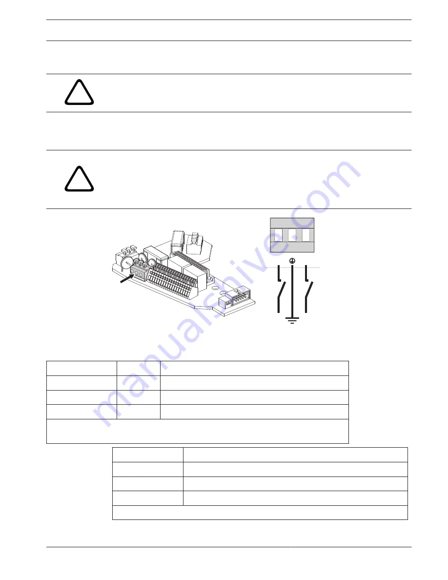
When the base is opened, the power supply board appears as shown below. To connect
the power supply, make the connections as seen in figure Power Supply Connections
below.
!
Warning!
For 24 VAC models intended for UL markets, use only a Class 2 UL listed power supply for all
models except the UPH-H-WDIR-24 (compliant with the local electrical codes). For UPH-H-
WDIR-24, the power must be provided by a UL listed power supply with a double insulation
transformer.
J6
L
N
Figure 5.7: Power Supply Connections
3.
To wire the power cable (not supplied), attach the appropriate colored wire to the
appropriate terminal. Use the tables below for reference.
Wire Color
Reference
24 VAC
1
Terminal Connection
Per local Installer
N
Neutral
Per local Installer
L
Live/Active
Green/Yellow
G
Earth
1. For 24 VAC models intended for UL markets, use only a Class 2 UL listed power supply for all models except the UPH-H-WDIR-24 (compliant with the local
electrical codes). For UPH-H-WDIR-24, the power must be provided by a UL listed power supply with a double insulation transformer.
Wire Color
120 / 230 VAC
2
Terminal Connection
Blue
Neutral
Brown
Live/Active
Green/Yellow
Earth
2. Use the appropriate junction box to connect the power supply line. Use a Class 2, UL listed power supply
High-Speed Positioning System
(HSPS)
Installing the High Speed Positioning System | en
27
Bosch Security Systems, Inc.
Operation Manual
2013.11 | 5.2 | F.01U.291.981
Summary of Contents for UPH Series
Page 1: ...High Speed Positioning System HSPS UPH Series ...
Page 2: ...en Operation Manual ...
Page 80: ......
Page 81: ......


