20
|
Technical description
UNIMAT
6 720 807 794 (2013/04)
3.3.5
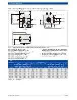
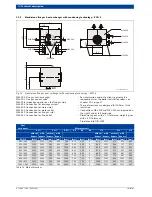
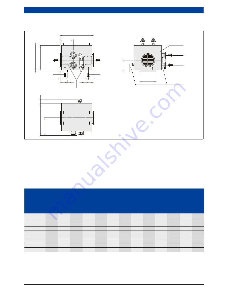
Stand-alone flue gas heat exchanger with condensing technology — ECO 6
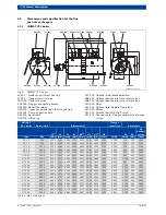
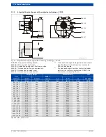
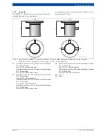
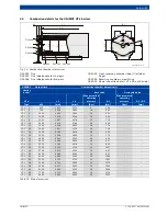
Fig. 12 Stand-alone flue gas heat exchanger with condensing technology – ECO 6
W32.000 Flue gas heat exchanger
W32.002 Flue gas control valve
W32.008 Inspection aperture on the flue gas side
W32.506 Connection for drainage system
W32.509 Connection for water inlet
W32.510 Connection for water outlet
W32.540 Connection for flue gas inlet
W32.541 Connection for flue outlet
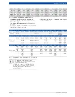
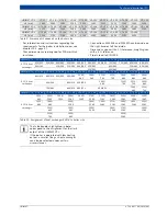
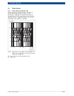
• For information and instructions regarding the
requirements for the boiler installation room, see
chapter 10.2, page 67.
• These dimensions are designed for 100-mm thick
insulation.
• Connections W32.509 and W32.510 can be made on
the right hand or left hand side.
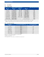
• Dimensions given with ± 1 % tolerance; weights given
with ± 3 % tolerance.
• Pipe thread to DIN 2999.
B1
B
4
B2
L 1
L 2
200
200
L 3
80
L 4
80
H3
W32.509
W32.000
W32.002
W32.008
W32.510
H2
H1
W32.506
W32.540
B 3
W32.507
W32.541
0-90°
0-90°
6 720 803 977-14.1itl
Heat
exchanger
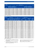
Measurements
L 1
1)
L 2
1)
B 1
2)
B 2
B 3
B 4
H 1
H 2
H 3
without
bypass
with
bypass
without
bypass
with
bypass
without
bypass
with
bypass
without
bypass
with
bypass
ECO 6
[mm]
[mm]
[mm]
[mm]
[mm]
[mm]
[mm]
[mm]
[mm]
[mm]
[mm]
[mm]
[mm]
390 / 260
1120
1235
560
600
794
475
300
0
874
1002
474
602
534
510 / 335
1120
1310
560
600
914
535
400
0
949
1117
549
717
572
600 / 385
1120
1360
560
600
1004
580
500
0
899
1067
599
767
497
690 / 460
1120
1435
560
600
1094
625
500
0
874
1072
674
872
434
750 / 485
1120
1460
560
600
1154
655
600
0
899
1097
699
897
447
850 / 560
1120
1685
560
750
1254
705
750
0
974
1197
774
997
484
890 / 610
1120
1623
560
638
1294
725
750
0
1024
1247
824
1047
509
930 / 635
1120
1648
560
638
1334
745
750
0
1049
1272
849
1072
522
1000 / 685
1520
1840
760
780
1404
780
750
0
1099
1417
899
1217
547
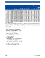
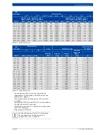
Table 13 Main dimensions


