58
|
System examples
UNIMAT
6 720 807 794 (2013/04)
9.5
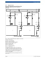
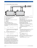
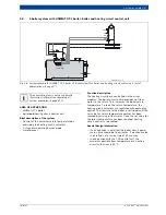
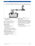
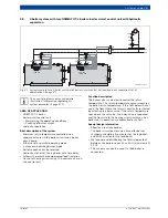
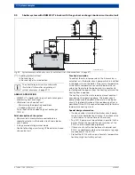
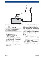
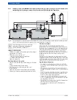
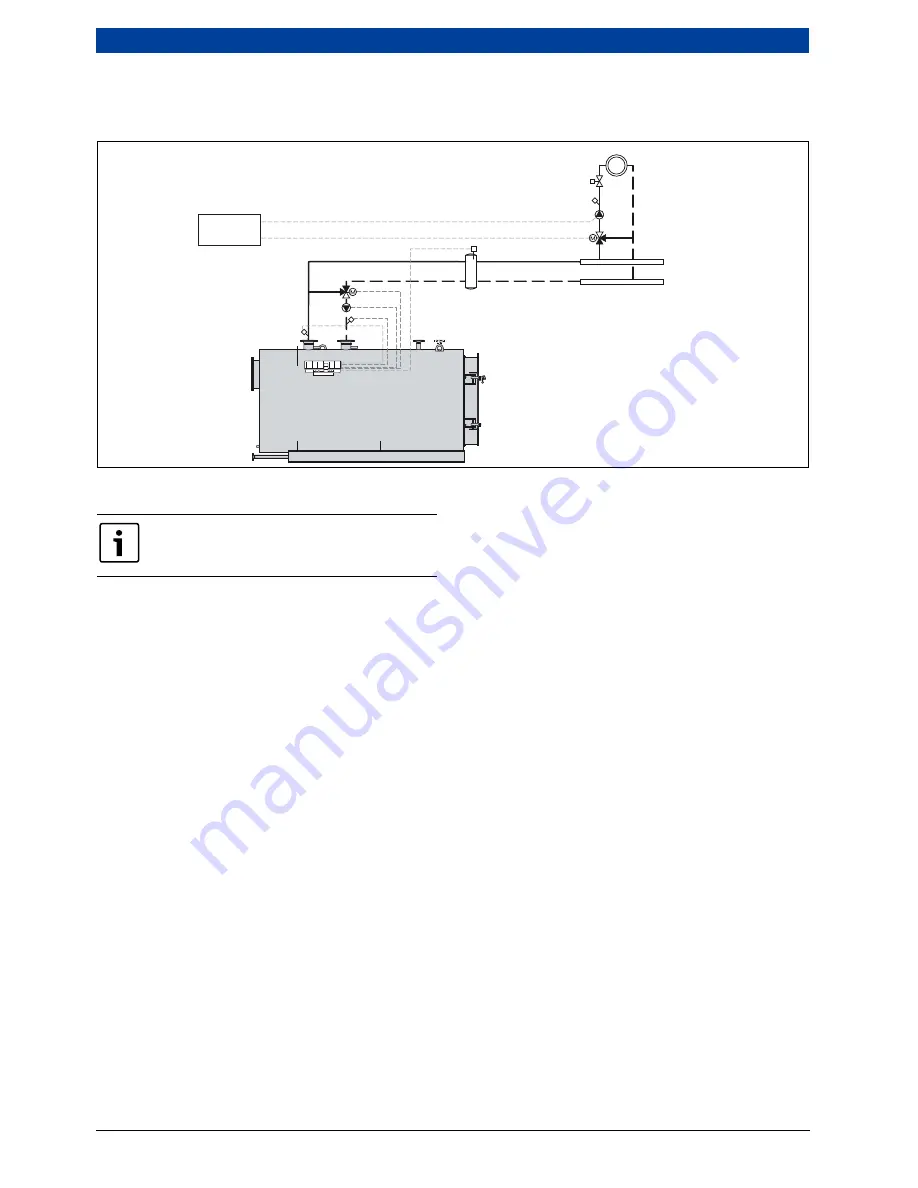
1-boiler system with UNIMAT UT-Lboiler: boiler and heating circuit control unit with hydraulic
separation
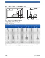
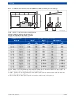
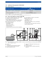
Fig. 39 System example with boiler and heating circuit control unit and hydraulic separation (list of abbreviations
page 47)
AREA OF APPLICATION
• UNIMAT UT-L boiler
• boiler
and
heating circuit control unit
• Hydraulic separation
• System structure in this form if a feed pump is
required, e.g. through sizing the heating circuit
pumps, or if several distributor stations are required,
or if the distributor stations are installed far apart
Brief description of the system
• Minimum return temperature controlled via a
separate actuator in the boiler circuit and a boiler
circuit pump
• 2-stage or modulating burner mode
• Automatic or weather-compensated load limitation
• Control of heating circuit using CFB control unit
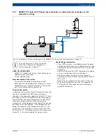
Function description
The 3-way valve is actuated to control the return
temperature. The return temperature sensor measures
the boiler return temperature. If this falls below the set
value, the flow rate to the heating return is constantly
restricted by actuating the 3-way valve. If the return
temperature rises above the set value, the 3-way valve is
reopened and the flow rate to the heating circuit
increases.
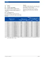
Special design information
• Size the boiler circuit pump for the maximum
calculated flow rate and the pressure loss in the
boiler circuit. Switch it to constant mode or set a run-
on time of 60 minutes.
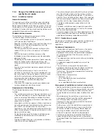
• Allow for a low loss header or a distributor with
bypass and non-return valve.
• In conjunction with the CFB control unit, the
maximum possible flow temperature of a heating
circuit with mixer is 90 °C.
HK
SH
PH
FV
THV
WH
6 720 803 977-19.1itl
CFB 930
+ CMC 930
+ CMM 920
DDC / GLT
RK
FZ
FVS
VK
PK
SR
FK
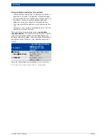
The circuit diagram is only a schematic
illustration! Information regarding all
system examples
page 47 ff.

