background image

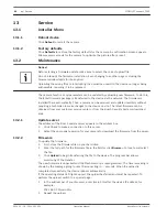
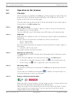
If you hover over the middle icon, the CPU load is shown.
If you hover over the right-hand icon, the network load is shown.
This information can help with problem solving or when fine tuning the unit. For example:

if the storage activity is too high, change the recording profile,

if the CPU load is too big, change the IVA settings,

if the network load is too big, change the encoder profile to reduce bitrate.

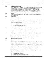
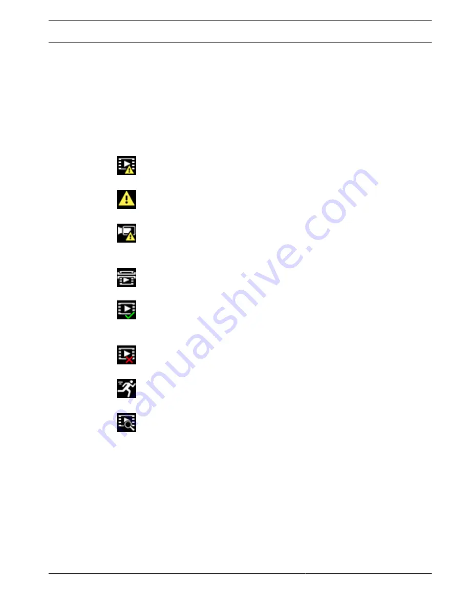
Status icons

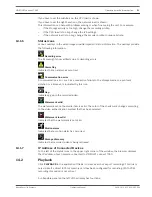
Various overlays in the video image provide important status information. The overlays provide
the following information:

 Decoding error

The frame might show artifacts due to decoding errors.

 Alarm flag

Indicates that an alarm has occurred.

 Communication error

A communication error, such as a connection failure to the storage medium, a protocol
violation or a timeout, is indicated by this icon.

 Gap

Indicates a gap in the recorded video.

 Watermark valid

The watermark set on the media item is valid. The color of the check mark changes according
to the video authentication method that has been selected.

 Watermark invalid

Indicates that the watermark is not valid.

 Motion alarm

Indicates that a motion alarm has occurred.

 Storage discovery

Indicates that recorded video is being retrieved.

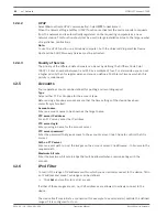
IP Address of Connected Devices

To the left of the status icons in the upper right corner of the window, the browser displays
the IP address of each camera connected to VIDEOJET connect 7000.

Playback

Click PLAYBACK in the application title bar to view, search or export recordings. This link is
only visible if a direct iSCSI or memory card has been configured for recording. (With VRM
recording this option is not active.)
 
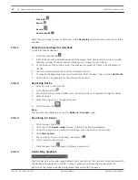
A collapsible panel on the left of the display has four tabs:

14.1.6

14.1.7

14.2

VIDEOJET connect 7000

Operation via the browser | en

51

Bosch Security Systems

Operation Manual

2014.10 | 1.4 | F.01U.291.524

Summary of Contents for VIDEOJET connect 7000

Page 1: ...VIDEOJET connect 7000 VJC 7000 90 en Operation Manual ...

Page 2: ......

Page 3: ...mensional Drawing 19 5 Installation 20 5 1 Mounting 20 5 2 Conduit Installation 22 5 3 PCBA Connections 23 5 4 Power Cable Installation 24 5 5 Ethernet Cables Installation 24 5 6 Fiber Installation 24 5 7 Alarm Inputs 25 5 8 Alarm Outputs 25 5 9 Washer Pump 25 5 10 Audio In and Out 26 5 11 Local Storage Media CF Card 26 5 12 Final Steps 26 6 Control of Connected Devices 27 6 1 System Requirements ...

Page 4: ...ystem log 33 9 Transcoder 34 9 1 Transcoder Setup 34 9 1 1 Device number 34 9 1 2 Name 34 9 1 3 Password 34 9 1 4 Http port Https port 34 9 1 5 Configure Router 34 9 2 Transcoder Profile 35 9 2 1 Profile name 35 9 2 2 Maximum bit rate 35 9 2 3 Transcoding interval 36 9 2 4 Video resolution 36 9 2 5 I frame distance 36 9 2 6 Min P frame QP 36 9 2 7 I P frame delta QP 36 9 3 Audio 37 10 Recording 38...

Page 5: ... 2 44 12 1 13 Network MSS Byte 44 12 1 14 iSCSI MSS Byte 44 12 1 15 Network MTU Byte 44 12 2 DynDNS 44 12 2 1 Enable DynDNS 44 12 2 2 Provider 44 12 2 3 Host name 44 12 2 4 User name 44 12 2 5 Password 44 12 2 6 Force registration now 45 12 2 7 Status 45 12 3 Advanced 45 12 3 1 Cloud based Services 45 12 3 2 RTSP port 45 12 3 3 Authentication 802 1x 45 12 4 Network Management 45 12 4 1 SNMP 45 12 ...

Page 6: ...P Address of Connected Devices 51 14 2 Playback 51 14 2 1 Selecting recordings for playback 52 14 2 2 Exporting tracks 52 14 2 3 Searching for tracks 52 14 2 4 Controlling playback 52 15 Configure VIDEOJET connect 7000 to Operate with a MIC7000 Camera 54 15 1 Configure Alarm Inputs and Outputs 54 15 2 Configure Audio 54 15 3 Configure Video Playback 54 16 Troubleshooting and Maintenance 55 16 1 Tr...

Page 7: ...be treated accordingly Safety Precautions In this manual the following symbols and notations are used to draw attention to special situations Danger High risk This symbol indicates an imminently hazardous situation such as Dangerous Voltage inside the product If not avoided this will result in an electrical shock serious bodily injury or death Caution Medium risk Indicates a potentially hazardous ...

Page 8: ...conductors location of discharge unit connection to grounding electrodes and requirements for the grounding electrode Heat sources Do not install unit near any heat sources such as radiators heaters or other equipment including amplifiers that produce heat Installation location The unit is intended only for installation in a Restricted Access Location Lightning For added protection during a lightn...

Page 9: ...devices this power source must comply with EN 60950 Substitutions may damage the device or cause fire or shock For 24 VAC devices voltage applied to the device s power input should not exceed 10 or 28 VAC User supplied wiring must comply with local electrical codes Class 2 power levels Do not ground the supply at the terminals or at the device s power supply terminals If unsure of the type of powe...

Page 10: ... area is likely to cause harmful interference in which case the user will be required to correct the interference at his expense Intentional or unintentional modifications not expressly approved by the party responsible for compliance shall not be made Any such modifications could void the user s authority to operate the equipment If necessary the user should consult the dealer or an experienced r...

Page 11: ...nter Telephone 585 421 4220 Fax 585 223 9180 or 717 735 6561 Email security repair us bosch com Canada Telephone 514 738 2434 Fax 514 738 8480 Europe Middle East Africa Region Please contact your local distributor or Bosch sales office Use this link http www boschsecurity com startpage html europe htm Asia Pacific Region Please contact your local distributor or Bosch sales office Use this link htt...

Page 12: ...n for connections to optional washer one 1 terminal plug connector 3 pin for AC mains power input one 1 terminal plug connector 6 pin for alarm inputs one 1 terminal plug connector 7 pin for alarm outputs and tamper switch three 3 watertight M16 cable glands with O rings Installation Manual Additional Tools Required Installers must provide the following items to complete installation of a MIC ALM ...

Page 13: ...d to the device The device provides the following features HD Base T PoH dedicated for one RJ45 Ethernet connection between the device and a Bosch IP camera powered by PoE High PoE a push button on the PBCA to allow users to activate test a connected washer pump accessory optional user supplied Ability to control connected cameras using the built in web browser of the device support for daisy chai...

Page 14: ...to the head end network Note The cable to the head end also can be fiber optic cable from one of the two SFP slots 3 Alarm input output interface cables user supplied 4 Alarm output cables user supplied 5 120 230 VAC 50 60 Hz 6 Audio input output interface cables user supplied 7 External washer pump user supplied 8 Washer output 2 conductor user supplied 3 1 14 en Product Overview VIDEOJET connect...

Page 15: ... Data only IP cable Cat5e Cat6e to the head end network Note The cable to the head end also can be fiber optic cable from one of the two SFP slots 3 Head end network 4 Daisy chain Data only IP cable Note The cable to the head end also can be fiber optic cable from one of the two SFP slots 5 120 230 VAC 50 60 Hz 6 Daisy chain Data only IP cable to the next VIDEOJET connect 7000 unit not shown 3 2 V...

Page 16: ...Data only IP cable Cat5e Cat6e between a Bosch IP camera and the port labeled ETH 2 on VIDEOJET connect 7000 3 Head end network 4 Data only IP cable Cat5e Cat6e between a Bosch camera and the port labeled ETH 1 on VIDEOJET connect 7000 5 Fiber optic cable to the head end network 6 Fiber optic cable to the next VIDEOJET connect 7000unit if applicable 3 3 16 en Product Overview VIDEOJET connect 7000...

Page 17: ...camera and the port labeled PoE on VIDEOJET connect 7000 2 Network switch user supplied 3 Head end network 4 Internet the cloud 5 Mobile device with Bosch video security app 6 Data only IP cable to the next VIDEOJET connect 7000 unit Note The cable also can be fiber optic cable from one of the two SFP slots 3 4 VIDEOJET connect 7000 Product Overview en 17 Bosch Security Systems Operation Manual 20...

Page 18: ...l 2 3 Vpp at 32 ohm typical 1 7 Vpp at 16 ohm typical Washer driver output Dry contact relay 250 V 5 A Communication Three 3 10BASE T 100BASE TX 1000Base TX If SFP fiber optic modules installed two 2 1000 BASE FX Push button Momentary switch to activate washer relay Local storage One 1 slot for optional CompactFlash CF memory card Type I Type II 32 GB max user supplied SFP small form factor plugga...

Page 19: ...Dimensional Drawing 13 in 330 mm 9 84 in 250 mm 3 57 in 90 75 mm 4 2 VIDEOJET connect 7000 Technical Data en 19 Bosch Security Systems Operation Manual 2014 10 1 4 F 01U 291 524 ...

Page 20: ... of the hub or fitting Note In these steps the item numbers in parentheses refer to the numbers in the figure in PCBA Connections page 23 1 Select a secure installation location for the device Ideally this is a location where the device cannot be interfered with intentionally or accidentally and that will ensure that environmental conditions are within the rated specifications Bosch recommends ins...

Page 21: ...l position for example on a wall one person should hold the enclosure lid while another person secures the enclosure body in place to avoid damage to any part of the enclosure and or injury to the installers VIDEOJET connect 7000 Installation en 21 Bosch Security Systems Operation Manual 2014 10 1 4 F 01U 291 524 ...

Page 22: ...plied for audio and or alarm inputs outputs or for fiber optic cable user supplied 5 Optional hole size M16 plugged for conduit user supplied for audio and or alarm inputs outputs or for fiber optic cable user supplied 6 Cable gland size M16 for data only IP cable Cat5e Cat6e user supplied or for fiber optic cable user supplied 7 Optional hole size M16 plugged for conduit user supplied for data on...

Page 23: ... Audio IN 7 Terminal plug connector 7 pin for alarm outputs and tamper switch 8 Terminal plug connector 6 pin for alarm inputs 9 One 1 slot for optional CompactFlash CF memory card Type I Type II 32 GB max user supplied 10 Two 2 slots for use with SFP based fiber optic modules 1GB only user supplied 11 Two 2 RJ45 Ethernet female ports labeled ETH1 ETH2 12 One 1 RJ45 HPoE Ethernet female port label...

Page 24: ...r conduit hole near the port labeled PoE on the PCBA item 12 Connect the cable to the port on the PCBA Note Do not remove the protective material over the PCBA 7 Connect network Ethernet cable s if applicable Feed an Ethernet cable Cat5e Cat6e rated to 350 MHz from the head end network through an appropriate cable gland or conduit hole near the RJ45 ports labeled ETH1 and ETH2 item 11 Connect the ...

Page 25: ...or to the appropriate location on the PCBA Alarm Outputs 10 Connect Alarm outputs if applicable Prepare the cable as needed Feed the cable through an appropriate cable gland or conduit hole near where the 7 pin terminal plug connector for alarm outputs will be installed on the PCBA item 7 Make the connections for relay outputs for switching external units such as lamps or alarm sirens to the conne...

Page 26: ... Storage Media CF Card 13 Install a CF card to save recordings locally if applicable Caution Bosch recommends disconnecting power to the unit whenever inserting or removing a CF card Carefully slide a CF card into the card slot item 9 as far as it will go until it locks into place Caution If the card is formatted already all existing data will be deleted from the card Before inserting the card che...

Page 27: ...b under Internet Options You can find notes on using Microsoft Internet Explorer in the online Help in Internet Explorer If you choose to use a computer running Microsoft Internet Explorer or any of the Bosch software the computer must conform to the following minimum requirements Operating System Windows XP Service Pack 3 or Windows 7 32 or 64 bits Processor Intel Pentium Quad Core 3 0 GHz or com...

Page 28: ... has been configured for recording With VRM recording this option is not active The LIVE page is used to display the live video stream and control the unit The PLAYBACK page is used for playing back recorded sequences The SETTINGS page is used to configure the unit and the application interface 6 2 28 en Control of Connected Devices VIDEOJET connect 7000 2014 10 1 4 F 01U 291 524 Operation Manual ...

Page 29: ... separated from it by a full stop You can see the initiator name in the System Overview page Password A password prevents unauthorized access to the device You can use different authorization levels to limit access Proper password protection is only guaranteed when all higher authorization levels are also protected with a password Therefore you always have to start from the highest authorization l...

Page 30: ...atically between normal and daylight saving time DST The unit already contains the data for DST switch overs for many years in advance If the date time and zone have been set up correctly a DST table is automatically created If you decide to create alternative daylight saving time dates by editing the table note that values occur in linked pairs DST start and end dates First check the time zone se...

Page 31: ... of a time server Time server type Select the protocol that is supported by the selected time server It is recommended to select the SNTP server protocol This protocol provides high accuracy and is required for special applications and future function extensions Select Time server if the server uses the RFC 868 protocol 7 3 5 7 3 6 VIDEOJET connect 7000 General settings en 31 Bosch Security System...

Page 32: ...n is displayed in the live video image With the MOTION analysis type for example the sensor fields in which motion is recorded are marked with rectangles Show VCA trajectories The trajectories motion lines of objects from the video content analysis are displayed in the live video image if a corresponding analysis type is activated Show overlay icons When selected various status icons are displayed...

Page 33: ...d with the date and time in a field next to the video image and provide information about the establishment and termination of connections and other system level messages Logging Save event log Select this option to save event messages in a text file on the local computer This file can be viewed edited and printed with any text editor or standard office software File for event log Enter the path f...

Page 34: ... to the camera or to the encoder on the corresponding SETTINGS page of the respective unit The name that you enter here will be displayed in the title bar of the transcoder Web pages and in the list of available cameras on the PLAYBACK page If you leave the field empty the IP address of the unit is displayed Password 4 In the field Password enter the service password of the selected camera Http po...

Page 35: ... Target bit rate 40 kbps Maximum bit rate 50 kbps Encoding interval 30 00 ips Modem Target bit rate 20 kbps Maximum bit rate 22 kbps Encoding interval 30 00 ips GSM Target bit rate 7 kbps Maximum bit rate 8 kbps Encoding interval 30 00 ips If required enter a new name for the profile Maximum bit rate This maximum data rate is not exceeded under any circumstances Depending on the video quality sett...

Page 36: ...rame QP value the higher the encoding quality and thus the best image quality and the lower the frame refresh rate depending on the settings for the maximum data rate under network settings A higher quantization value results in low image quality and lower network load Typical QP values are between 18 and 30 The basic setting Auto automatically adjusts the quality to the settings for the P frame v...

Page 37: ...io Input volume You can set the input volume with the slider from 0 to 31 with 0 as the default 9 3 VIDEOJET connect 7000 Transcoder en 37 Bosch Security Systems Operation Manual 2014 10 1 4 F 01U 291 524 ...

Page 38: ... indicator it cannot be changed here If the Managed by VRM box is checked you are not able to configure any further recording settings on this page Recording media Select a media tab to connect to the available storage media iSCSI Media To use an iSCSI system as the storage medium a connection to the desired iSCSI system is required to set the configuration parameters The storage system selected m...

Page 39: ...ick Format in the new window to delete all recordings in the storage medium 4 Click OK to close the window Deactivating storage media A storage medium in the Managed storage media list can be deactivated It is then no longer used for recordings 1 Click a storage medium in the Managed storage media list to select it 2 Click Remove below the list The storage medium is deactivated and removed from th...

Page 40: ...for RAM recording together with a minimum post alarm time are selected all available alarm triggers are activated and metadata is included in recording Continuous The best stream profile is selected for recording pre and post alarm times are deleted all available alarm triggers are deactivated and metadata is included in recording Recording Scheduler The scheduler is set to 24 7 recording with the...

Page 41: ...This will overwrite all settings and entries on the other alarm pages 1 Click Examples under the Alarm Task Editor field to see some script examples A new window opens 2 Enter new scripts in the Alarm Task Editor field or change existing scripts in line with your requirements 3 When finished click Set to transmit the scripts to the device If the transfer was successful the message Script successfu...

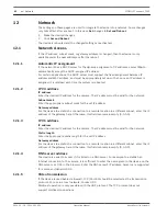
Page 42: ... connection to a remote location in a different subnet enter the IP address of the gateway here Otherwise this field can remain empty 0 0 0 0 IP V6 address IP address Enter the desired IP address for the camera The IP address must be valid for the network Prefix length Enter the appropriate prefix length for the set IP address Gateway address For the device to establish a connection to a remote lo...

Page 43: ...et the Off option to deactivate the port Telnet support Activating Telenet support allows unencrypted connections on this port To allow only encrypted connections set the Off option to deactivate telnet support making telnet connections impossible Interface mode PoE Select the type of Ethernet link for the interface for the camera bound to VIDEOJET connect 7000 connected to the port labeled PoE on...

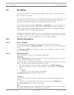
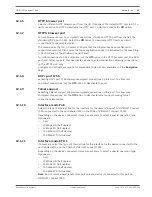
Page 44: ...nds on the network structure A higher value is only useful if the iSCSI system is located in the same subnet as the camera Network MTU Byte Specify a maximum value in bytes for the package size including IP header to optimize data transmission DynDNS Enable DynDNS A dynamic Domain Name Service DNS allows you to select the unit via the Internet using a host name without having to know the current I...

Page 45: ...802 1x To configure Radius server authentication connect the unit directly to a computer using a network cable If a Radius server controls access rights over the network select On to activate authentication to communicate with the unit 1 Enter the user name that the Radius server uses for the unit in the Identity field 2 Enter the Password that the Radius server expects from the unit Network Manag...

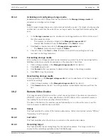
Page 46: ...opbox account ensure that the time settings of the device have been correctly synchronized Account name Enter an account name to be shown as the target name FTP server IP address For an FTP server enter the IP address FTP server login Enter your login name for the account server FTP server password Enter the password that gives access to the account server Click Check to confirm that it is correct...

Page 47: ...yption If an encryption license is installed this submenu gives access to the encryption parameters 12 7 VIDEOJET connect 7000 Network en 47 Bosch Security Systems Operation Manual 2014 10 1 4 F 01U 291 524 ...

Page 48: ...center or from the Bosch Security Systems download area Update server The address of the Bosch update server appears in the address box 1 Click Check to make a connection to this server 2 Select the appropriate version for your camera to download the firmware from the server Firmware To update the firmware 1 First store the firmware file on your hard disk 2 Enter the full path for the firmware fil...

Page 49: ...e name if required and save Maintenance log Download an internal maintenance log from the device to send it to Customer Service for support purposes Click Save As and select a storage location for the file Licenses This window is for the activation of additional functions by entering activation codes An overview of installed licenses is shown The installation code of the unit is also displayed her...

Page 50: ... when the output is activated System Log Event Log The System Log field contains information about the operating status of the camera and the connection Events such as the triggering or the end of alarms are shown in the Event Log field 1 To view filter and save these messages to a file click in the top right hand corner 2 To clear the log click in the top right hand corner of the relevant field R...

Page 51: ...ap Indicates a gap in the recorded video Watermark valid The watermark set on the media item is valid The color of the check mark changes according to the video authentication method that has been selected Watermark invalid Indicates that the watermark is not valid Motion alarm Indicates that a motion alarm has occurred Storage discovery Indicates that recorded video is being retrieved IP Address ...

Page 52: ...e are filled in for the selected track If required change the times 4 Select a target 5 Select the original or a condensed speed 6 Click the save icon Note The target server address is set on the Network Accounts page Searching for tracks 1 Click the search tab 2 Click one of the Search mode options to define the search parameters 3 To limit the search to a particular time range enter the start an...

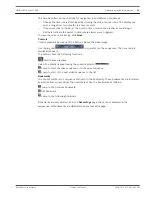
Page 53: ... above it The buttons have the following functions Start Pause playback Select the playback speed using the speed regulator Jump to start of active sequence or to previous sequence Jump to start of the next video sequence in the list Bookmarks You can set markers in a sequence and jump to these directly These bookmarks are indicated as small yellow arrows above the time interval Use the bookmarks ...

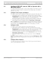
Page 54: ... 7000 the camera for which the value in the field Application variant is set to camera name VJC 7000 Configure Audio To configure a camera bound to channel 1 for audio follow these steps 4 On the camera bound to VIDEOJET connect 7000 verify that the value in the field Application variant is set to camera name VJC 7000 Access the field from Camera Installer Menu in the web browser of the camera Thi...

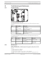
Page 55: ...cator Description Resolution 1 Red flashing Fault for example firmware upload failed Reload firmware 3 4 5 6 7 No light from LED Off not powered Check power connections Maintenance Damage requiring service Unplug the devices from the main AC power source and refer servicing to qualified service personnel whenever any damage to the device has occurred such as the power supply cable is damaged an ob...

Page 56: ... attempt to service this device yourself Refer all servicing to qualified service personnel 56 en Troubleshooting and Maintenance VIDEOJET connect 7000 2014 10 1 4 F 01U 291 524 Operation Manual Bosch Security Systems ...

Page 57: ...Technical data For more specific product details see the VIDEOJET connect 7000 datasheet 17 VIDEOJET connect 7000 Technical data en 57 Bosch Security Systems Operation Manual 2014 10 1 4 F 01U 291 524 ...

Page 58: ......

Page 59: ......
Page 60: ...Bosch Security Systems Inc 850 Greenfield Road Lancaster PA 17601 USA www boschsecurity com Bosch Security Systems Inc 2014 Bosch Sicherheitssysteme GmbH Robert Bosch Ring 5 85630 Grasbrunn Germany ...

Reviews: