background image

VPV Vane Pump

25

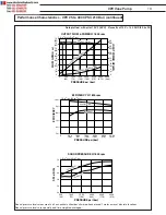
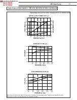
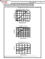
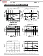
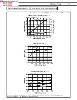
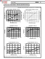
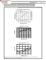
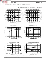
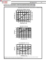
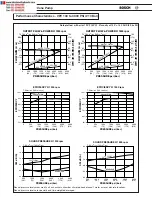
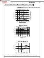
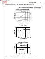
Performance Characteristics - VPV 130 to 3000 PSI (210 Bar) (continued)

Data plotted:  with oil at 120°F (49°C)   Viscosity at 120° = 140 SUS (29.6 cSt)

75

(284)

45

(171)

 30

(114)

 15

(57)

 60

(227)

150

(112)

90

(67)

 60

(45)

 30

(22)

 120

(90)

  0

  0

 0

500

(34)

1000

(70)

1500

(104)

2000

(140)

2500

(174)

3000

(210)

3500

(244)

PRESSURE psi (bar)

FLOW GPM (L/m)

INPUT POWER HP (kW)

OUTPUT FLOW & POWER @ 1800 rpm

7.93 in

3

/rev (130cm

3

/rev)

DEADHEAD HORSEPOWER

INPUT HO

RSEP

OWER

OUTPUT FLOW

100%

60%

80%

90%

70%

50%

0

500

(34)

1500

(104)

1000

(70)

2000

(140)

2500

(170)

3000

(210)

EFFICIENCY

PRESSURE psi (bar)

EFFICIENCY @ 1800 rpm

7.93in

3

/rev (130cm

3

/rev)

OVERALL

VOLUMETRIC

80

68

72

76

64

60

500

(34)

1000

(70)

1500

(104)

2000

(140)

2500

(170)

3000

(210)

SPL dB (A)

PRESSURE psi (bar)

SOUND PRESSURE @ 1800 rpm

7.93 in

3

/rev (130cm

3

/rev)

FULL FLOW

DEADHEAD

Sound pressure levels measured in a hemi-anchoic chamber w/microphone placed 1 meter away at discrete locations.
Sound pressure levels are spacially and time-weighted averaged.

Summary of Contents for VPV 100

Page 1: ...Hydraulics VPV Vane Pump Service and Repair Guide ...

Page 2: ... D flange RH rotation Installation Drawing 39 VPV 100 130 164 Single pump Metric flange RH rotation Installation Drawing 41 VPV 16 Combination pump S A E A flange RH rotation Installation Drawing 43 VPV 25 32 Combination pump S A E B flange RH rotation Installation Drawing 44 VPV 32 16 Combination pump S A E B flange RH rotation Installation Drawing 45 VPV 32 25 Combination pump S A E F Gear pump ...

Page 3: ... with shock clipper 10 Conforms to the latest SAE ISO NFPA and ANSI standards 11 Combination capability full horsepower may be transferred to pump 2 Combinations of construction of multiple pumps may be required to be de rated LOW COST Competitively priced with other manufacturers of vane pumps and economy axial piston pumps EXCEPTIONALLY QUIET Helps machinery builders meet government and purchase...

Page 4: ...overhung or side loads permitted Alignments greater than 006 indicator reading could cause increased noise and vibration as well as premature shaft seal wear resulting in leakage Fluid recommendations A premium quality hydraulic oil with anti wear additives is recommended but not required Refer to publication S 106 Petroleum Hydraulic Fluids for a list of fluids which meet or exceed the necessary ...

Page 5: ... overhung or side loads permitted Alignments greater than 006 indicator reading could cause increased noise and vibration as well as premature shaft seal wear resulting in leakage Fluid recommendations A premium quality hydraulic oil with anti wear additives is recommended but not required Refer to publication S 106 Petroleum Hydraulic Fluids for a list of fluids which meet or exceed the necessary...

Page 6: ...de loads permitted Alignments greater than 006 indicator reading could cause increased noise and vibration as well as premature shaft seal wear resulting in leakage Fluid recommendations A premium quality hydraulic oil with anti wear additives is required Refer to publica tion S 106 Petroleum Hydraulic Fluids for a list of fluids which meet or exceed the necessary lubrication requirements Consult ...

Page 7: ...uction V Variable displacement pump open circuit K Fixed Displacement Pump available in 1998 9 Displacement 16 16 cc rev 98 cu in rev 25 25 cc rev 1 53 cu in rev 32 32 cc rev 1 95 cu in rev 45 45 cc rev 2 75 cu in rev 63 63 cc rev 3 84 cu in rev 80 80 cc rev 4 88 cu in rev 100 100 cc rev 6 10 cu in rev 130 130 cc rev 7 93 cu in rev 164 164 cc rev 10 00 cu in rev Item No 1 2 3 4 5 6 7 8 9 10 11 12 ...

Page 8: ...nect compression fitting w sentinel light XE 115V N O w flying leads XF 220V N O w flying leads XG 12V N O w flying leads XH 24V N O w flying leads XJ 115V N O w DIN 43650 NG6 XK 220V N O w DIN 43650 NG6 XL 12V N O w DIN 43650 NG6 XM 24V N O w DIN 43650 NG6 XN 115V N O w flying leads NG6 XO 220V N O w flying leads NG6 XP 12V N O w flying leads NG6 XR 24V N O w flying leads NG6 Solenoid Operated Tw...

Page 9: ...ect compression fitting w sentinel light WD 24V N C w DIN 43650 quick connect compression fitting w sentinel light WE 115V N C w flying leads WF 220V N C w flying leads WG 12V N C w flying leads WH 24V N C w flying leads 14 Accessories S Special Consult Factory Y Maximum delivery limiter Z No other accessories 15 B01 Design Series P1 Pump 1 of a quick combination unit adapter kit coupling required...

Page 10: ...re line graphs of the Performance Characteristics for each of the pumps in our series Characteristics are shown at 1200 PSI 1500 PSI and 3000 PSI Since different geographical areas require different data please refer to the appropriate graph ...

Page 11: ...AD HORSEPOWER 100 10 60 80 90 70 50 40 30 20 0 0 500 34 1500 104 1000 70 2000 140 2500 170 3000 210 EFFICIENCY PRESSURE psi bar EFFICIENCY 1200 rpm 1 in3 rev 16cm3 rev VOLUMETRIC OVERALL 100 10 60 80 90 70 50 40 30 20 0 0 500 34 1500 104 1000 70 2000 140 2500 170 3000 210 EFFICIENCY PRESSURE psi bar EFFICIENCY 1500 rpm 1 in3 rev 16cm3 rev VOLUMETRIC OVERALL 70 54 62 66 58 50 500 34 1000 70 1500 10...

Page 12: ... rev OUTPUT FLOW INPUT HORSEPOW ER DEADHEAD HORSEPOWER 100 10 60 80 90 70 50 40 30 20 0 0 500 34 1500 104 1000 70 2000 140 2500 170 3000 210 EFFICIENCY PRESSURE psi bar EFFICIENCY 1800 rpm 1 in3 rev 16cm3 rev VOLUMETRIC OVERALL 70 54 62 66 58 50 500 34 1000 70 1500 104 2000 140 2500 170 3000 210 SPL dB A PRESSURE psi bar SOUND PRESSURE 1800 rpm 1 in3 rev 16cm3 rev FULL FLOW DEADHEAD Sound pressure...

Page 13: ... ER DEADHEAD HORSEPOWER OUTPUT FLOW 100 80 90 70 60 50 0 500 34 1000 70 1500 104 3000 210 2500 170 2000 140 EFFICIENCY PRESSURE psi bar EFFICIENCY 1200 rpm 1 5 in3 rev 25cm3 rev VOLUMETRIC OVERALL 100 80 90 70 60 50 0 500 34 1000 70 1500 104 3000 210 2500 170 2000 140 EFFICIENCY PRESSURE psi bar EFFICIENCY 1500 rpm 1 5 in3 rev 25cm3 rev VOLUMETRIC OVERALL 70 54 62 66 58 50 500 34 1000 70 1500 104 ...

Page 14: ...5 in3 rev 25cm3 rev OUTPUT FLOW INPUT HORSEPOW ER DEADHEAD HORSEPOWER 100 80 90 70 60 50 0 500 34 1000 70 1500 104 3000 210 2500 170 2000 140 EFFICIENCY PRESSURE psi bar EFFICIENCY 1800 rpm 1 5 in3 rev 25cm3 rev VOLUMETRIC OVERALL 70 54 62 66 58 50 500 34 1000 70 1500 104 2000 140 2500 170 3000 210 SPL dB A PRESSURE psi bar SOUND PRESSURE 1800 rpm 1 5 in3 rev 25cm3 rev FULL FLOW DEADHEAD Sound pre...

Page 15: ...EPOW ER DEADHEAD HORSEPOWER 100 80 90 70 60 50 0 500 34 1000 70 1500 104 3000 210 2500 170 2000 140 EFFICIENCY PRESSURE psi bar EFFICIENCY 1200 rpm 2 in3 rev 32cm3 rev VOLUMETRIC OVERALL 100 80 90 70 60 50 0 500 34 1000 70 1500 104 3000 210 2500 170 2000 140 EFFICIENCY PRESSURE psi bar EFFICIENCY 1500 rpm 2 in3 rev 32cm3 rev VOLUMETRIC OVERALL 70 54 62 66 58 50 500 34 1000 70 1500 104 2000 140 250...

Page 16: ...v 32cm3 rev OUTPUT FLOW INPUT HORSEPOW ER DEADHEAD HORSEPOWER 100 80 90 70 60 50 0 500 34 1000 70 1500 104 3000 210 2500 170 2000 140 EFFICIENCY PRESSURE psi bar EFFICIENCY 1800 rpm 2 in3 rev 32cm3 rev VOLUMETRIC OVERALL 70 54 62 66 58 50 500 34 1000 70 1500 104 2000 140 2500 170 3000 210 SPL dB A PRESSURE psi bar SOUND PRESSURE 1800 rpm 2 in3 rev 32cm3 rev FULL FLOW DEADHEAD Sound pressure levels...

Page 17: ...SEPOW ER OUTPUT FLOW 100 60 80 90 70 50 0 500 34 1500 104 1000 70 2000 140 2500 170 3000 210 EFFICIENCY PRESSURE psi bar EFFICIENCY 1200 rpm 2 75 in3 rev 45cm3 rev VOLUMETRIC OVERALL 100 60 80 90 70 50 0 500 34 1500 104 1000 70 2000 140 2500 170 3000 210 EFFICIENCY PRESSURE psi bar EFFICIENCY 1500 rpm 2 75 in3 rev 45cm3 rev VOLUMETRIC OVERALL 80 68 72 76 64 60 500 34 1000 70 1500 104 2000 140 2500...

Page 18: ...m3 rev DEADHEAD HORSEPOWER INPUT HO RSEPO W ER OUTPUT FLOW 100 60 80 90 70 50 0 500 34 1500 104 1000 70 2000 140 2500 170 3000 210 EFFICIENCY PRESSURE psi bar EFFICIENCY 1800 rpm 2 75 in3 rev 45cm3 rev VOLUMETRIC OVERALL Sound pressure levels measured in a hemi anchoic chamber w microphone placed 1 meter away at discrete locations Sound pressure levels are spacially and time weighted averaged 80 6...

Page 19: ...OW GPM L m INPUT POWER HP kW OUTPUT FLOW POWER 1500 rpm 3 84 in3 rev 63cm3 rev DEADHEAD HORSEPOWER INPUT HORSEPOW ER OUTPUT FLOW 100 60 80 90 70 50 0 500 34 1500 104 1000 70 2000 140 2500 170 3000 210 EFFICIENCY PRESSURE psi bar EFFICIENCY 1200 rpm 3 84in3 rev 63cm3 rev OVERALL VOLUMETRIC 100 60 80 90 70 50 0 500 34 1500 104 1000 70 2000 140 2500 170 3000 210 EFFICIENCY PRESSURE psi bar EFFICIENCY...

Page 20: ...84 in3 rev 63cm3 rev DEADHEAD HORSEPOWER INPUT HO RSEPO W ER OUTPUT FLOW 100 60 80 90 70 50 0 500 34 1500 104 1000 70 2000 140 2500 170 3000 210 EFFICIENCY PRESSURE psi bar EFFICIENCY 1800 rpm 3 84in3 rev 63cm3 rev OVERALL VOLUMETRIC 80 68 72 76 64 60 500 34 1000 70 1500 104 2000 140 2500 170 3000 210 SPL dB A PRESSURE psi bar SOUND PRESSURE 1800 rpm 3 84 in3 rev 63cm3 rev FULL FLOW DEADHEAD Sound...

Page 21: ...URE psi bar EFFICIENCY 1200 rpm 4 90in3 rev 80cm3 rev OVERALL VOLUMETRIC 100 60 80 90 70 50 0 500 34 1500 104 1000 70 2000 140 2500 170 3000 210 EFFICIENCY PRESSURE psi bar EFFICIENCY 1500 rpm 4 90in3 rev 80cm3 rev OVERALL VOLUMETRIC 80 68 72 76 64 60 500 34 1000 70 1500 104 2000 140 2500 170 3000 210 SPL dB A PRESSURE psi bar SOUND PRESSURE 1200 rpm 4 90 in3 rev 80cm3 rev FULL FLOW DEADHEAD 80 68...

Page 22: ... EFFICIENCY PRESSURE psi bar EFFICIENCY 1800 rpm 4 90n3 rev 80cm3 rev OVERALL VOLUMETRIC 80 68 72 76 64 60 500 34 1000 70 1500 104 2000 140 2500 170 3000 210 SPL dB A PRESSURE psi bar SOUND PRESSURE 1800 rpm 4 90 in3 rev 80cm3 rev DEADHEAD FULL FLOW Sound pressure levels measured in a hemi anchoic chamber w microphone placed 1 meter away at discrete locations Sound pressure levels are spacially an...

Page 23: ... rev DEADHEAD HORSEPOWER INPUT HORSEPOW ER OUTPUT FLOW 100 60 80 90 70 50 0 500 34 1500 104 1000 70 2000 140 2500 170 3000 210 EFFICIENCY PRESSURE psi bar EFFICIENCY 1200 rpm 6 1in3 rev 100cm3 rev OVERALL VOLUMETRIC 100 60 80 90 70 50 0 500 34 1500 104 1000 70 2000 140 2500 170 3000 210 EFFICIENCY PRESSURE psi bar EFFICIENCY 1500 rpm 6 1in3 rev 100cm3 rev OVERALL VOLUMETRIC 80 68 72 76 64 60 500 3...

Page 24: ...m 6 1 in3 rev 100cm3 rev DEADHEAD HORSEPOWER INPUT HORSEPOW ER OUTPUT FLOW 100 60 80 90 70 50 0 500 34 1500 104 1000 70 2000 140 2500 170 3000 210 EFFICIENCY PRESSURE psi bar EFFICIENCY 1800 rpm 6 1in3 rev 100cm3 rev OVERALL VOLUMETRIC 80 68 72 76 64 60 500 34 1000 70 1500 104 2000 140 2500 170 3000 210 SPL dB A PRESSURE psi bar SOUND PRESSURE 1800 rpm 6 1 in3 rev 100cm3 rev FULL FLOW DEADHEAD Sou...

Page 25: ...D HORSEPOWER INPUT HORSEPOW ER OUTPUT FLOW 100 60 80 90 70 50 0 500 34 1500 104 1000 70 2000 140 2500 170 3000 210 EFFICIENCY PRESSURE psi bar EFFICIENCY 1200 rpm 7 93in3 rev 130cm3 rev OVERALL VOLUMETRIC 100 60 80 90 70 50 0 500 34 1500 104 1000 70 2000 140 2500 170 3000 210 EFFICIENCY PRESSURE psi bar EFFICIENCY 1500 rpm 7 93in3 rev 130cm3 rev OVERALL VOLUMETRIC 80 68 72 76 64 60 500 34 1000 70 ...

Page 26: ...in3 rev 130cm3 rev DEADHEAD HORSEPOWER INPUT HORSEPOW ER OUTPUT FLOW 100 60 80 90 70 50 0 500 34 1500 104 1000 70 2000 140 2500 170 3000 210 EFFICIENCY PRESSURE psi bar EFFICIENCY 1800 rpm 7 93in3 rev 130cm3 rev OVERALL VOLUMETRIC 80 68 72 76 64 60 500 34 1000 70 1500 104 2000 140 2500 170 3000 210 SPL dB A PRESSURE psi bar SOUND PRESSURE 1800 rpm 7 93 in3 rev 130cm3 rev FULL FLOW DEADHEAD Sound p...

Page 27: ... 500 34 1500 104 1000 70 2000 140 2500 170 3000 210 EFFICIENCY PRESSURE psi bar EFFICIENCY 1200 rpm 10 0in3 rev 164cm3 rev OVERALL 100 60 80 90 70 50 0 500 34 1500 104 1000 70 2000 140 2500 170 3000 210 OVERALL VOLUMETRIC 100 60 80 90 70 50 0 500 34 1500 104 1000 70 2000 140 2500 170 3000 210 EFFICIENCY PRESSURE psi bar EFFICIENCY 1500 rpm 10 0in3 rev 164cm3 rev OVERALL 100 60 80 90 70 50 0 500 34...

Page 28: ... rev 164cm3 rev 100 60 80 90 70 50 0 500 34 1500 104 1000 70 2000 140 2500 170 3000 210 EFFICIENCY 1800 rpm VOLUMETRIC OVERALL 80 68 72 76 64 60 500 34 1000 70 1500 104 2000 140 2500 170 3000 210 SPL dB A PRESSURE psi bar SOUND PRESSURE 1800 rpm 10 in3 rev 164cm3 rev FULL FLOW DEADHEAD Sound pressure levels measured in a hemi anchoic chamber w microphone placed 1 meter away at discrete locations S...

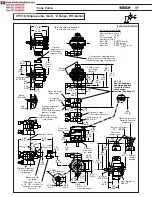
Page 29: ...2 0 Rotation arrows cast into body 4 56 115 8 1 83 46 6 4 59 116 7 4 65 118 1 3 50 88 7 3 92 99 7 2 00 51 0 1 65 42 0 Optional 2 pressure solenoid operated compensator Optional 2 pressure vent solenoid operated compensator Spline See data 30 Involute Spline Data Flat root side fit Class 5 Pitch 16 32 Pressure angle 30 Number of teeth 9 Base Dia 0 487193 in ref Form Dia 0 504 in ref Major Dia 0 625...

Page 30: ...Optional 2 pressure solenoid operated compensator Optional 2 pressure vent solenoid operated compensator 1 2 conduit connector Pump centerline Manual override pushpin Centerline pump control Centerline pump control 2 66 67 5 3 36 85 0 Pump centerline Compensator adjusting knob CW rotation increases pressure standard single stage compensator Optional volume control CW rotation reduces flow Pump con...

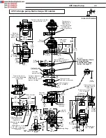
Page 31: ...4 206 8 4 65 118 0 1 36 34 5 Pump centerline Pump control mounting datum T Optional volume control CW rotation reduces flow 1 61 41 0 0 31 7 8 0 56 14 2 Outlet port 16 S A E 4 46 113 4 5 26 133 7 max 0 36 9 25 1 57 40 0 2 36 59 7 30 Involute Spline Data Flat root side fit Pitch Pressure angle Number of teeth Base dia Form dia Major dia Class 5 16 32 30 13 0 703645 in ref 0 749 in ref 0 875 0 000 i...

Page 32: ...enterline of pump control 1 08 27 5 1 83 46 6 Load sense port 1 4 19 BSPP 4 88 123 9 4 16 105 8 210 bar 3 84 97 7 140 bar 3 53 89 7 7 16 179 4 Optional 2 pressure operated solenoid compensator 9 06 230 1 8 39 213 2 6 84 173 8 Manual override pushpin Remote control port 1 4 19 BSPP Optional 2 stage compensator 2 stage compensator adjusting knob CW rotation increases pressure setting 4 59 116 7 4 65...

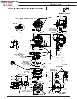
Page 33: ...r 6 94 176 3 7 85 199 3 2 36 59 7 Centerline of pump control 1 08 27 5 1 83 46 6 Load sense port 1 4 19 BSPP 4 88 123 9 4 16 105 8 210 bar 3 84 97 7 140 bar Remote control port 4 SAE Optional 2 stage compensator 2 stage compensator adjusting knob CW rotation increases pressure setting Optional 2 stage load compensator Centerline of pump control Rotation arrows cast into body Centerline of pump con...

Page 34: ...36 9 25 0 36 9 25 0 31 14 2 Outlet port 16 SAE 4 46 113 3 5 96 151 4 5 26 133 7 max 1 57 40 0 5 17 131 4 2 05 52 0 Remote control port 4 SAE 3 78 95 9 5 75 146 0 0 56 14 4 S A E B mounting flange ø4 00 ø101 6 5 17 131 4 7 06 179 4 3 53 89 7 7 05 179 3 3 79 96 3 Pump centerline Rotation arrows cast into body 4 65 118 1 2 03 51 7 3 63 92 2 4 59 116 7 Optional DIN 43650 connector w 1 2 NPT compressio...

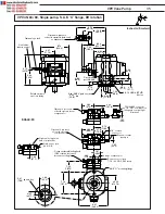
Page 35: ...al volume control CW rotation reduces flow 0 31 7 8 0 56 14 2 Outlet port 16 S A E 4 46 113 4 5 26 133 7 max 6 60 167 6 0 36 9 25 1 57 40 0 2 36 59 7 5 17 131 4 4 65 118 1 8 25 209 5 10 16 258 1 11 05 280 6 8 38 212 9 5 11 129 7 1 2 14 NPTF threaded connection 16 00 406 5 0 47 12 0 0 96 24 3 Optional 2 stage compensator w NG6 pressure select valve wiring box Pump centerline 2 stage compensator adj...

Page 36: ...erline pump control 1 39 35 2 3 82 97 0 4 24 107 8 3 89 99 0 2 78 70 8 4 70 119 4 ø1 25 ø31 7 0 31 square key 7 98 9 31 236 5 ø5 00 ø127 0 1 67 42 5 1 67 42 5 SAE C mounting flange 7 30 185 5 7 13 181 0 Compensator adjusting knob CW rotation increases pressure setting SCALE 2X 0 69 17 6 2 66 67 7 1 91 48 6 Optional 2 pressure solenoid operated vent compensator Optional 2 pressure solenoid operated...

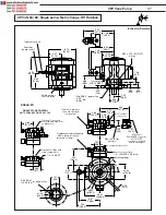
Page 37: ...36 VPV Vane Pump VPV 45 63 80 Single pump S A E C flange RH rotation continued Inches millimeters ...

Page 38: ... 26 ø32 0 0 39 X 0 31 rectangular key 10 0 X 8 0 ø9 31 ø236 5 6 61 168 0 7 44 189 0 1 67 42 5 1 65 42 0 Mounting flange Compensator adjusting knob CW rotation increases pressure setting SCALE 2X 1 91 48 6 SINGLE STAGE CONTROL NOT AVAILABLE ON VPV 45 164 Optional 2 pressure solenoid operated compensator Manual override pushpin 1 2 conduit connector Optional DIN 43650 connector w 1 2 NPT compression...

Page 39: ...um T Pump centerline Pump centerline Optional volume control CW rotation reduces flow Support Lift point M10 X 1 5 6H X 11 25 deep TH D 5 36 136 2 10 55 267 9 Optional combination capable pump with end cover P1 Version 9 64 244 9 2 04 51 7 1 19 30 2 0 59 15 1 2 31 58 7 1 16 29 4 2 70 68 5 0 36 9 2 0 41 10 5 Std SAE 1 1 4 pad pressure 1 25 dia 31 8 M12 x 1 75 6H TH D 4 holes 3 76 95 7 Inches millim...

Page 40: ...verride pushpin 1 2 conduit connector Optional DIN 43650 connector w 1 2 NPT compression fitting and sentinal light Optional 2 stage with load compensator Load sense port 4 S A E 2 stage compensator Remote control port 7 16 20 UNF 0 45 deep ø6 00 ø152 4 12 80 325 0 0 81 20 7 typ 8 41 213 7 SAE D mounting flange 8 62 219 1 9 00 229 0 Compensator adjusting knob CW rotation increases pressure setting...

Page 41: ...Optional volume control CW rotation reduces flow Lift point M10 x 1 5 6H x 11 0 deep th d 6 20 157 4 12 90 327 8 12 00 304 8 1 82 46 3 1 41 35 9 0 70 17 9 2 75 69 9 1 37 34 9 Std S A E 1 1 2 pad pressure 1 46 dia 37 1 2 96 75 1 0 49 12 4 0 32 8 1 1 2 13 UNC 28 deep 4 holes Pump control mounting datum T Pump centerline Pump centerline Optional combination capable pump with end cover P1 Version Inch...

Page 42: ...al override pushpin 1 2 conduit connector Optional DIN 43650 connector w 1 2 NPT compression fitting and sentinal light Optional 2 stage with load compensator 1 4 19 BSPP 2 stage compensator Remote control port 1 4 19 BSPP 0 48 deep 12 80 325 0 8 41 213 7 Mounting flange 8 62 219 1 Compensator adjusting knob CW rotation increases pressure setting 5 77 146 6 11 53 292 9 12 11 307 6 6 06 153 8 4 39 ...

Page 43: ...l volume control CW rotation reduces flow Lift point M10 x 1 5 6H x 11 0 deep th d 6 20 157 4 12 90 327 8 12 00 304 8 1 86 47 3 1 41 35 9 0 70 17 9 2 75 69 9 1 37 34 9 Std S A E 1 1 2 pad pressure 1 46 dia 37 1 3 62 92 1 0 40 10 1 0 36 9 2 M12 x 1 75 28 deep 4 holes Pump control mounting datum T Pump centerline Pump centerline Optional combination capable pump with end cover P1 Version Inches mill...

Page 44: ...96 176 8 11 94 303 4 12 61 320 2 12 61 320 2 4 56 115 8 3 19 81 0 2 80 71 3 4 11 104 5 5 61 142 5 0 83 21 1 ø748 ø19 0 shaft dia 4 19 106 4 0 43 11 1 0 188 square key 4 8 S A E A 2 bolt mounting flange Remote control 4 S A E 3 90 99 0 Inlet port 16 S A E Case drain port 8 S A E Inlet port 16 S A E Case drain port 8 S A E Support Lift point 3 8 16UNC 2B X 22 0mm deep 1 08 27 5 4 65 118 0 7 45 189 2...

Page 45: ... 14 74 374 5 16 55 420 5 13 35 339 2 3 86 98 0 11 07 281 1 14 08 357 7 8 12 206 3 1 57 40 0 Remote control 4 S A E 4 58 116 5 Inlet port 24 S A E Case drain port 8 S A E Inlet port 24 S A E Case drain port 8 S A E Support Lift point 3 8 16UNC 2B X 22 0mm deep 3 53 89 7 7 06 179 4 4 90 124 3 4 65 118 0 1 08 27 5 4 65 118 0 5 44 138 2 9 90 251 5 11 73 297 9 6 S A E Shock clipper port Should be plumb...

Page 46: ...compensator adjusting knob CW rotation increases pressure rating Compensator adjusting knob CW rotation increases pressure rating Standard single stage compensator 4 65 118 0 8 14 206 8 5 53 140 5 12 79 324 9 10 27 260 9 7 81 198 3 4 58 116 4 Remote control port 4 S A E 6 63 168 6 3 86 98 0 12 06 306 4 14 92 379 0 13 37 339 7 5 24 133 3 A A B B 2 35 59 7 7 06 179 4 3 53 89 7 3 35 85 0 11 55 293 4 ...

Page 47: ...thru support holes 0 4 10 2 3 33 84 6 2 61 66 4 0 4 10 2 Standard single stage compensator Centerline pump control ø4 00 ø101 6 Rotation arrow cast into body 1 65 41 9 Pump centerline Pump centerline Outlet port inlet port opposite side Compensator adjusting knob CW rotation increases pressure setting 3 78 96 0 Pump control mounting datum T Inches millimeters Gear Pump Dimension Total Weight Theor...

Page 48: ... 44 87 5 2 81 71 3 2 81 71 3 76 19 2 1 53 38 89 Inlet port std SAE 2 pad ø2 00 ø50 8 3 06 77 78 0 84 21 44 2 04 51 7 1 69 42 88 4 00 101 5 Case drain port METRIC 3 8 19 BSPP SAE 8 S A E SAE C 2 bolt mounting flange per ISO 3019 1 69 17 6 5 96 151 4 13 03 330 8 DETAIL SAE SAE DETAIL METRIC METRIC 2 08 52 8 2 08 52 8 16 80 426 8 10 50 266 8 13 62 346 0 ø 47 thru support hole ø12 0 16 14 410 0 Inlet ...

Page 49: ...TRIC1 SAE 7 16 14UNC 2B TH D X 1 14 deep typ METRIC M12 X 1 75 6H TH D 29 0 4 holes 1 16 29 36 2 31 58 72 59 15 09 1 19 30 18 5 36 136 2 13 62 346 0 10 50 266 8 Outlet port Std SAE 1 1 4 pad ø1 25 ø31 8 Suport Lift point SAE METRIC M10 X 1 5 6H TH D X 44 deep 11 2 Suport point SAE 3 8 16 UNC 2B TH D X 59 deep 15 0 METRIC M10 X 1 5 6H TH D X 59 deep 15 0 Optional volume control CW rotation reduces ...

Page 50: ... 123 9 1 08 27 5 16 78 426 4 Inlet Inlet Remote control A A VIEW A A Optional 2 stage compensator 2 stage compensator 2 stage compensator adjusting knob CW rotation increases pressure setting Centerline pump control 6 S A E Shock Clipper port Should be plumbed to tank to activate shock clipper function See page 97 Inches millimeters ...

Page 51: ...4 51 7 1 69 42 88 4 00 101 5 Case drain port METRIC 3 8 19 BSPP SAE 8 S A E SAE C 2 bolt mounting flange per ISO 3019 1 69 17 6 5 96 151 4 13 03 330 8 DETAIL SAE SAE DETAIL METRIC METRIC 2 08 52 8 2 08 52 8 18 01 457 5 10 82 274 9 14 41 366 1 8 14 206 8 3 53 89 7 4 19 106 4 3 53 89 7 ø 47 thru support hole ø12 0 17 43 442 6 Inlet port SAE 24 S A E METRIC 1 1 2 11 BSPP Compensator adjusting knob CW...

Page 52: ...3 8 19 BSPP 4 65 118 0 9 90 251 5 5 44 138 2 6 89 174 9 max See detail SAE1 METRIC1 SAE 7 16 14UNC 2B TH D X 1 14 deep typ METRIC M12 X 1 75 6H TH D 29 0 4 holes 1 16 29 36 2 31 58 72 59 15 09 1 19 30 18 5 36 136 2 14 41 366 2 10 82 274 9 5 26 133 7 max Support point SAE 3 8 16UNC 2B TH D X 87 deep METRIC M10 X 1 5 6H TH D 22 0 Suport Lift point SAE METRIC M10 X 1 5 6H TH D X 44 deep 11 2 Optional...

Page 53: ...8 123 9 1 08 27 5 18 07 459 0 Inlet Inlet Remote control A A VIEW A A Optional 2 stage compensator 2 stage compensator 2 stage compensator adjusting knob CW rotation increases pressure setting Centerline pump control 6 S A E Shock Clipper port Should be plumbed to tank to activate shock clipper function See page 97 Inches millimeters ...

Page 54: ...t mounting flange per ISO 3019 1 69 17 6 5 96 151 4 13 03 330 8 DETAIL SAE SAE DETAIL METRIC METRIC 2 08 52 8 2 08 52 8 C A B 10 50 266 7 ø 47 thru support hole ø12 0 Support point SAE 3 8 16UNC 2B TH D X 59 deep METRIC M10 X 1 5 TH D 15 0 SAE 1 2 13UNC 2B TH D X 1 14 deep typ METRIC M12 X 1 75 6H TH D 29 0 4 holes SAE METRIC SAE METRIC A B A B SH 2 K 6 SH 2 D 6 4 94 125 4 3 33 84 6 2 61 66 4 0 4 ...

Page 55: ...ent A B C D E F Gear Pump in3 rev in in in in in in Inlet Outlet lbs cc rev mm mm mm mm mm mm Kg 0 24 1 571 3 346 13 30 15 08 13 56 15 35 9 16 18 UNF 9 16 18 UNF 135 4 39 9 85 0 337 8 383 2 344 6 390 0 61 2 0 34 1 618 3 445 13 35 15 19 13 62 15 45 9 16 18 UNF 9 16 18 UNF 135 2 5 5 41 1 87 5 339 1 385 7 345 9 392 5 61 3 0 49 1 697 3 606 13 43 15 34 13 70 15 61 7 8 14 UNF 7 8 14 UNF 135 4 8 43 2 91 ...

Page 56: ...150 0 1 37 34 9 ø1 26 ø32 0 0 39 X 0 31 rectangular key 10 0 X 8 0 G 4 37 111 0 8 74 222 0 5 76 146 2 10 13 257 2 5 96 151 4 13 03 330 8 2 08 52 8 E A B ø 47 thru support hole ø12 0 METRIC METRIC 4 94 125 4 3 33 84 6 2 61 66 4 0 4 10 2 Compensator adjusting knob CW rotation increases pressure setting Outlet port Inlet port opposiete sides Inches millimeters ...

Page 57: ...SAE C 2 bolt mounting flange per ISO 3019 1 69 17 6 5 96 151 4 13 03 330 8 DETAIL SAE SAE DETAIL METRIC METRIC 2 08 52 8 2 08 52 8 C A B 10 50 266 7 ø 47 thru support hole ø12 0 Support point SAE 3 8 16UNC 2B TH D X 87 deep METRIC M10 X 1 5 6H TH D 22 0 SAE 1 2 13UNC 2B TH D X 1 14 deep typ METRIC M12 X 1 75 6H TH D 29 0 4 holes SAE METRIC SAE METRIC A B A B SH 2 K 6 SH 2 D 6 4 94 125 4 4 19 106 4...

Page 58: ...l CW rotation reduces flow Inches millimeters Gear pump Total Weight Theoretical Dimension Gear Pump Port Sizes Vane Pump Displacement A B C D Gear Pump in3 rev in in in in Inlet Outlet lbs cc rev mm mm mm mm Kg 1 37 2 40 5 07 14 6 17 26 1 S A E 3 4 S A E 271 4 22 5 61 0 128 5 370 8 438 6 4 bolt 4 bolt 123 1 1 71 2 48 5 26 14 68 17 45 1 S A E 3 4 S A E 271 8 28 63 0 133 7 372 8 443 2 4 bolt 4 bolt...

Page 59: ...eep typ METRIC M12 x 1 75 6H TH D 29 0 4 holes 3 06 typ 77 78 1 69 typ 42 88 0 84 typ 21 44 2 04 typ 51 7 Case drain port METRIC 3 8 19 BSPP typ SAE 8 S A E typ 4 37 111 0 7 30 185 5 8 00 203 1 4 37 111 0 5 76 146 2 10 13 257 2 4 94 125 4 18 38 466 8 23 18 588 8 ø 69 thru support hole ø17 5 5 22 132 6 Compensator adjusting knob CW rotation increases pressure setting 17 33 440 3 15 48 393 1 11 12 2...

Page 60: ... 80 477 6 Support Lift point SAE METRIC M10 X 1 5 6H TH D X 44 deep typ 11 2 Support point SAE 5 8 11 UNC 2b TH D X 1 30 deep typ METRIC M16 x 2 6H TH D 33 0 Optional volume control CW rotation reduces flow Outlet port Std S A E 1 1 4 pad ø1 25 typ ø31 8 6 89 174 9 max 2 04 51 7 2 31 58 72 1 16 29 36 SAE 7 16 14UNC 2B TH D X 1 14 deep typ METRIC M12 X 1 75 6H TH D 29 0 4 holes See detail SAE1 METR...

Page 61: ...es pressure setting 1 91 48 6 2 stage compensator Remote control port 7 16 20 UNF 0 45 11 4 deep Compensator adjusting knob CW rotation increases pressure setting 1 91 48 6 2 stage compensator Remote control port 1 4 19 UNF 0 48 12 2 deep 6 61 168 0 7 44 189 0 3 82 97 0 4 24 107 8 3 89 99 0 2 78 70 8 4 70 119 4 1 67 42 5 2 66 67 7 Optional 2 pressure solenoid operated vent compensator Optional 2 p...

Page 62: ...yp 51 7 Case drain port METRIC 3 8 19 BSPP typ SAE 8 S A E typ 4 37 111 0 7 48 190 0 9 03 229 4 9 72 247 0 4 37 111 0 10 13 257 2 4 94 125 4 18 38 466 8 23 18 588 8 5 22 132 6 Compensator adjusting knob CW rotation increases pressure setting 17 33 440 3 15 48 393 1 11 12 282 4 4 00 typ 101 5 Support point SAE 5 8 11UNC 2B TH D X 1 30 deep METRIC M16 X 2 6H TH D 33 0 Optional 2 pressure solenoid op...

Page 63: ...load sense compensator Load sense port S A E 4 SAE Metric 1 4 19 BSPP 0 70 18 0 1 85 46 9 45 12 80 325 0 12 80 325 0 ø7 87 ø200 0 METRIC 4 bolt mounting flange per ISO 3019 2 ø1 57 ø40 0 47 square key 12 0 44 square key 11 1 81 20 7 ø1 75 ø44 42 S A E D 2 bolt mounting flange per ISO 3019 1 9 00 229 0 1 94 49 3 DETAIL SAE SAE DETAIL METRIC METRIC Compensator adjusting knob CW rotation increases pr...

Page 64: ... drain SAE 8 S A E typ METRIC 3 8 19 BSPP 3 77 typ 95 7 2 24 57 0 0 95 24 0 Inlet port Std S A E 2 1 2 pad ø2 47 typ ø62 7 4 39 111 6 typ 3 50 88 9 typ 1 75 44 5 typ 2 00 50 8 typ 1 00 25 4 typ SAE 1 2 13UNC 2B TH D X 1 10 deep METRIC M12 X 1 75 6H TH D 28 0 Support point SAE 5 8 11UNC 2B TH D X 1 30 deep METRIC M16 X 2 6H TH D 33 0 Compensator adjusting knob CW rotation increases pressure setting...

Page 65: ...1 71 3 5 77 146 6 4 72 120 0 12 87 326 9 15 99 484 4 18 51 470 1 ø 69 thru support hole ø17 5 Case drain SAE 8 S A E METRIC 3 8 19 BSPP Case drain SAE 8 S A E METRIC 3 8 19 BSPP 2 24 57 0 0 96 24 4 Inlet port Std S A E 2 1 2 pad ø2 47 typ ø62 7 Inlet port SAE 16 S A E METRIC 1 11 BSPP 3 93 111 6 3 50 88 9 1 75 44 5 2 00 50 8 1 00 25 4 SAE 1 2 13UNC 2B TH D X 1 10 deep METRIC M12 X 1 75 6H TH D 28 ...

Page 66: ...nt SAE 3 8 16 UNC 2B TH D X 59 deep 15 0 METRIC M10 x 1 5 6H TH D X 59 deep 15 0 Optional volume control CW rotation reduces flow Outlet port Std S A E 1 1 2 pad ø1 46 ø37 1 4 81 122 3 max 1 86 47 3 2 75 69 9 1 38 34 9 SAE 1 2 13UNC 2B TH D X 1 10 deep METRIC M12 X 1 75 6H TH D 28 0 See detail SAE1 METRIC1 94 23 8 6 50 165 1 Optional VPV25 32 single stage compensator with locking device Control dr...

Page 67: ... 15 486 4 Inlet port 6 93 176 0 4 21 106 9 6 23 158 4 Remote control Optional 2 stage compensator Centerline pump control 2 stage compensator adjusting knob CW rotation increases pressure setting 9 36 237 8 8 67 220 2 5 77 146 6 4 88 123 9 1 08 27 5 Inches millimeters ...

Page 68: ... METRIC 3 8 19 BSPP 2 24 57 0 0 96 24 4 Inlet port Std S A E 2 1 2 pad ø2 47 ø62 7 3 93 111 6 3 50 88 9 1 75 44 5 2 00 50 8 1 00 25 4 SAE 1 2 13UNC 2B TH D X 1 10 deep METRIC M12 X 1 75 6H TH D 28 0 Support Lift point SAE 3 8 16UNC 2B TH D X 87 deep 22 0 87 deep METRIC M10 X 1 5 6H TH D X 22 0 Compensator adjusting knob CW rotation increases pressure setting DETAIL SAE SAE DETAIL METRIC METRIC SAE...

Page 69: ...SAE 3 8 16 UNC 2B TH D X 87 deep 22 0 METRIC M10 x 1 5 6H TH D X 87 deep 22 0 Optional volume control CW rotation reduces flow Outlet port Std S A E 1 1 2 pad ø1 46 ø37 1 5 26 133 7 max 1 86 47 3 2 75 69 9 1 37 34 9 SAE 1 2 13UNC 2B TH D X 1 10 deep METRIC M12 X 1 75 6H TH D 28 0 See detail SAE1 METRIC1 94 23 8 6 50 165 1 Optional VPV25 32 single stage compensator with locking device Control drain...

Page 70: ...nlet port 7 33 186 2 4 65 118 1 6 63 168 6 Remote control Optional 2 stage compensator Shock clipper drain 2 stage compensator adjusting knob CW rotation increases pressure setting 2 stage compensator 9 36 237 8 8 67 220 2 5 77 146 6 4 88 123 9 1 08 27 5 View A A Inches millimeters ...

Page 71: ...1 75 6H TH D 28 0 Support point SAE 3 8 16UNC 2B TH D X 1 30 deep 33 0 1 30 deep METRIC M10 X 1 5 6H TH D X 33 0 Compensator adjusting knob CW rotation increases pressure setting DETAIL SAE SAE DETAIL METRIC METRIC SAE METRIC SAE METRIC A B A B SH 2 K 6 SH 2 C 6 T 7 65 194 2 7 27 184 7 16 08 408 5 7 65 194 2 7 27 184 7 16 08 408 5 25 54 648 8 4 S A E Optional 2 stage load sense compensator 2 66 67...

Page 72: ...yp METRIC M12 x 1 75 6H TH D typ Optional volume control CW rotation reduces flow 6 89 174 9 max 1 86 47 3 2 75 69 9 1 37 34 9 SAE 1 2 13UNC 2B TH D X 1 10 deep METRIC M12 X 1 75 6H TH D 28 0 See detail SAE1 METRIC1 Outlet port Std SAE 1 1 4 pad ø1 25 ø31 8 Support Lift point SAE METRIC M10 X 1 5 6H TH D X 43 deep 11 0 Support Lift point SAE METRIC M10 X 1 5 6H TH D X 43 deep 11 0 Support point SA...

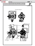
Page 73: ...72 VPV Vane Pump VPV 100 130 164 to VPV 45 63 80 continued 5 77 146 6 20 74 526 8 2 stage compensator Inlet port 8 00 203 1 7 30 185 5 9 36 237 8 8 67 220 2 Inches millimeters ...

Page 74: ...nlet port Std S A E 2 1 2 pad ø2 47 ø62 7 3 93 111 6 3 50 88 9 1 75 44 5 2 00 50 8 1 00 25 4 SAE 1 2 13UNC 2B TH D X 1 10 deep METRIC M12 X 1 75 6H TH D 28 0 Support point SAE 3 8 16UNC 2B TH D X 59 deep 15 0 59 deep METRIC M10 X 1 5 6H TH D X 15 0 Compensator adjusting knob CW rotation increases pressure setting DETAIL SAE SAE DETAIL METRIC METRIC SAE METRIC SAE METRIC A B A B SH 2 K 6 T 7 65 194...

Page 75: ... Sizes Vane Pump Displacement A B C D Gear Pump in3 rev in in in in Inlet Outlet lbs cc rev mm mm mm mm Kg 0 24 1 571 3 346 15 66 17 44 9 16 18 UNF 9 16 18 UNF 252 4 39 9 85 0 397 8 443 2 114 3 0 34 1 618 3 445 15 71 17 55 9 16 18 UNF 9 16 18 UNF 252 2 5 5 41 1 87 5 399 0 445 8 114 4 0 49 1 697 3 606 15 79 17 70 7 8 14 UNF 7 8 14 UNF 252 4 8 43 2 91 6 401 0 449 6 114 5 0 67 1 850 3 803 15 94 17 86...

Page 76: ... 111 6 3 50 88 9 1 75 44 5 2 00 50 8 1 00 25 4 SAE 1 2 13UNC 2B TH D X 1 10 deep METRIC M12 X 1 75 6H TH D 28 0 Support point SAE 3 8 16UNC 2B TH D X 87 deep 22 0 87 deep METRIC M10 X 1 5 6H TH D X 22 0 Outlet port 3 4 S A E 4 bolt pad Inlet port 1 S A E oposite side 4 bolt pad Compensator adjusting knob CW rotation increases pressure setting DETAIL SAE SAE DETAIL METRIC METRIC SAE METRIC SAE METR...

Page 77: ... Lift point SAE METRIC M10 X 1 5 6H TH D X 43 deep 11 0 8 57 217 7 max Inches millimeters Gear pump Total Weight Theoretical Dimension Gear Pump Port Sizes Vane Pump Displacement A B C D Gear Pump in3 rev in in in in Inlet Outlet lbs cc rev mm mm mm mm Kg 1 37 2 40 5 07 17 0 19 60 1 S A E 3 4 S A E 271 4 22 5 61 0 128 5 430 8 498 4 4 bolt 4 bolt 123 1 1 71 2 48 5 26 17 04 19 80 1 S A E 3 4 S A E 2...

Page 78: ...or VPV 45 164 PUMP OUTPUT INPUT CASE DRAIN P STC remote port Load Sense Compensator Load sense allows the user to maintain constant flow regardless of changes in load or in pump shaft rotational speed The Whisper Pump load sense accomplishes this by using an external orifice and continually senses a pressure drop of 100 PSI across this orifice The mini mum P is 200 PSI however the pressure drop ca...

Page 79: ...nsators are similar to the two pres sure controls except that there is no adjustment possible By venting the compensator the pump will go to minimum deadhead PUMP OUTPUT INPUT CASE DRAIN P STC REMOTE PORT Torque Limiting Compensator Torque limiting for VPV limits the input torque to the pump shaft in effect limiting the horsepower transmitted to the load No torque or horsepower sensing is done on ...

Page 80: ...30 Very quiet Typical living room 40 Office classroom 50 VPV16 1200 rpm 500 psi deadhead 49 dB Normal conversation 60 Moderate Automobile interior 70 VPV130 1800 rpm 3000 psi full flow 76 dB Urban street 80 Noisy Heavy truck 15 m 90 Very noisy Shout 1 5 m 100 Construction site 110 Loud rock music 120 Threshold of pain Jet airplane 150 Intolerable Rocket engine 180 ...

Page 81: ...g of the vane slots is required 10 Vane is installed incorrectly 10 In vane pumps built up to and including SV series 62 and VPV series 00 and A02 vanes must be mounted with the rounded edge toward the ring In SV series 72 and VPV series B01 and later the leading edge of the vanes must be oriented in the direction of rotation The leading edge is identified as the low side of the vane taper 11 A va...

Page 82: ...25 32 9 511 230 540 VPV SAE 100 130 164 to VPV 25 32 9 511 230 541 VPV Metric 100 130 164 to VPV 16 9 511 230 542 VPV SAE 100 130 164 to VPV 16 9 511 230 543 VPV Metric SAE 100 130 164 to SAE F Gear 9 511 230 554 VPV Metric SAE 32 25 to SAE G Gear 9 511 230 594 VPV Metric SAE 100 130 164 to SAE G Gear 9 511 230 590 VPV Metric SAE 100 130 164 to SAE B Spline ADAPTER KITS REF DESCRIPTION 32 Coupling...

Page 83: ...lead VPV pump can generate see chart EXAMPLES VPV 100 3045 psig VPV 63 3045 psig VPV 25 3045 psig 88 8 hp 58 5 hp 23 3 hp VPV 116 3045 psig VPV 16 1500 psig VPV 16 1500 psig 17 6 hp 8 7 hp 8 7 hp Flow 1750 Maximum Pump 1 Maximum Input RPM Pressure Input Power for other Pump gpm psig Horsepower pumps VPV 16 8 03 3000 17 6 17 6 VPV 25 12 6 3000 25 3 25 3 VPV 32 15 4 3000 30 7 30 7 VPV 45 21 8 3000 4...

Page 84: ...ning at full flow and low pressure while observing output flow Pump Nominal Decrease in Minimum Flow Model Stroke Flow Per Turn Attainable VPV 16 1 9 mm 0 075 53 0 VPV 25 2 0 mm 0 080 50 0 VPV 32 2 5 mm 0 099 40 20 VPV 45 1 9 mm 0 077 80 0 VPV 63 2 7 mm 0 106 56 8 VPV 80 3 4 mm 0 132 44 26 VPV 100 3 0 mm 0 117 50 17 VPV 130 3 8 mm 0 150 40 34 VPV 164 4 7 mm 0 186 32 47 ...

Page 85: ... cover 1 8 Thrust screw 1 9 Lock nut 1 10 Shaft 1 11 Retaining ring VPV 16 1 12 Bearing 2 Repair kits consists of REF DESC VPV16 VPV25 32 QTY 13 O ring ASA 111 ASA 111 1 14 O ring ASA 110 ASA 110 1 15 O ring ASA 127 ASA 136 2 16 O ring ASA 128 ASA 128 1 17 O ring ASA 026 ASA 028 2 18 O ring ASA 151 ASA 152 2 19 O ring ASA 031 ASA 031 1 20 O ring ASA 156 ASA 160 1 21 Back up ring 2 22 Shaft seal 1 ...

Page 86: ... VPV 16 Apply loctite sealant 569 to bore inistall to depth shown COVER BEARING BODY BEARING INSTALLATION NOTES OUT IN 883 TORQUE TO 300 LB IN 34 Nm TORQUE TO 300 LB IN 34 Nm TORQUE TO 700 LB IN 79 Nm TORQUE TO 960 LB IN 108 Nm 4 5 6 2 1 3 TORQUE RATINGS REF DESCRIPTION QTY 1 O ring 011 75 1 2 Back up ring 1 3 Piston 1 4 Body 1 5 Adjusting screw 1 6 Jam nut 1 Assembly consists of VOLUME CONTROL AS...

Page 87: ...28 75 1 7 O ring 111 75 1 8 Poppet second stage 1 10 Plug w O ring 1 11 O ring 910 75 1 12 O ring 908 75 1 13 Back up ring 1 14 O ring 1 15 Poppet seat w O ring 1 COMPLETE ASSSEMBLY FOR TWO STAGE COMPENSATOR SAE 9 511 230 514 METRIC 9 511 230 515 COMPLETE ASSEMBLY FOR LOAD SENSE SAE 9 511 230 600 METRIC Consult factory REPAIR KIT FOR TWO STAGE COMPENSATOR SAE 9 511 230 624 METRIC 9 511 230 516 Rep...

Page 88: ...rque to 80 100 Nm Torque to 44 62 lb in Torque to 5 7 Nm Pressure adjustment lock nut REF DESCRIPTION QTY 1 O ring ASA 113 1 2 Back up ring 1 3 O ring 1 4 O ring ASA 111 3 5 O ring ASA 143 1 6 O ring 15 3 i d x 2 4mm c s 1 7 O ring ASA 111 1 8 Back up ring 1 9 O ring ASA 011 2 10 Poppet 1 11 Poppet seat w O ring 1 12 Plug w O ring 1 COMPLETE ASSSEMBLY FOR TWO STAGE COMPENSATOR SAE 9 511 230 550 ME...

Page 89: ...t block kit 1 7 Bearing 2 8 Spacer ring 1 9 Pressure ring 1 10 Port plate body side 1 Repair kits consists of REF DESC VPV45 80 VPV100 164 QTY 13 O ring ASA 031 ASA 035 2 14 O ring ASA 162 ASA 265 1 15 O ring ASA 130 ASA 229 1 16 O ring ASA 146 ASA 146 1 17 Shaft seal 1 18 O ring ASA 229 ASA 237 1 19 O ring ASA 110 ASA 110 1 20 O ring ASA 111 ASA 111 3 21 O ring ASA 143 ASA 143 1 22 O ring ASA 157...

Page 90: ...1 VANE PUMP COMBO CAPABLE 22 4 3 2 8 9 10 15 14 16 17 6 18 1 21 20 19 VPV 45 63 80 Torque to 1800 lb in Torque to 204 Nm Torque to 850 lb in Torque to 96 Nm Torque to 850 lb in Torque to 96 Nm Torque to 12 lb in Torque to 1 4 Nm 7 24 23 5 13 VPV 100 130 164Torque to 4970 lb in Torque to 562 Nm ...

Page 91: ... ring 1 Port plate body side 1 Repair kits consists of Viton seal kits consist of 3000 PSI Repair Parts VPV 16 25 32 4 6 1 3 7 2 5 REF DESCRIPTION QTY 1 O ring 011 75 1 2 Back up ring 1 3 Piston 1 4 Body 1 5 Adjusting screw 1 6 Jam nut 1 7 O Ring ASA 113 1 Repair kits consists of VOLUME CONTROL ASSEMBLY 9 537 232 004 All o rings durmoeter rating 75 Desc VPV16 VPV25 32 QTY O ring ASA 111 ASA 111 1 ...

Page 92: ... 75 1 13 Back up ring 1 14 O ring 1 15 Poppet seat w O ring 1 COMPLETE ASSSEMBLY FOR TWO STAGE COMPENSATOR SAE 9 511 230 601 METRIC 9 511 230 602 COMPLETE ASSEMBLY FOR LOAD SENSE SAE 9 511 230 603 METRIC 9 511 230 604 REPAIR KIT FOR TWO STAGE COMPENSATOR SAE 9 511 230 627 METRIC 9 511 230 628 Repair kit consists of TWO STAGE COMPENSATOR SINGLE STAGE COMPENSATOR See above view for location of Ref 1...

Page 93: ... VPV 16 Apply loctite sealant 569 to bore inistall to depth shown COVER BEARING BODY BEARING INSTALLATION NOTES OUT IN 883 TORQUE TO 300 LB IN 34 Nm TORQUE TO 300 LB IN 34 Nm TORQUE TO 700 LB IN 79 Nm TORQUE TO 960 LB IN 108 Nm 4 5 6 2 1 3 TORQUE RATINGS REF DESCRIPTION QTY 1 O ring 011 75 1 2 Back up ring 1 3 Piston 1 4 Body 1 5 Adjusting screw 1 6 Jam nut 1 Assembly consists of VOLUME CONTROL AS...

Page 94: ...ment lock nut REF DESCRIPTION QTY 1 O ring ASA 113 1 2 Back up ring 1 3 O ring 1 4 O ring ASA 111 3 5 O ring ASA 143 1 6 O ring 15 3 i d x 2 4mm c s 1 7 O ring ASA 111 1 8 Back up ring 1 9 O ring ASA 011 2 10 Poppet 1 11 Poppet seat w O ring 1 12 Plug w O ring 1 COMPLETE ASSSEMBLY FOR TWO STAGE COMPENSATOR SAE 9 511 230 610 METRIC 9 511 230 611 COMPLETE ASSEMBLY FOR LOAD SENSE SAE 9 511 230 612 ME...

Page 95: ...pin 4 6 Thrust block kit 1 7 Bearing 2 8 Spacer ring 1 9 Pressure ring 1 10 Port plate body side 1 Repair kits consists of REF DESC VPV45 80 VPV100 164 QTY 13 O ring ASA 031 ASA 035 2 14 O ring ASA 162 ASA 265 1 15 O ring ASA 130 ASA 229 1 16 O ring ASA 146 ASA 146 1 17 Shaft seal 1 18 O ring ASA 229 ASA 237 1 19 O ring ASA 110 ASA 110 1 20 O ring ASA 111 ASA 111 3 21 O ring ASA 143 ASA 143 1 22 O...

Page 96: ...VPV Vane Pump 95 Vane Tip Orientation R o t ation Looking into pump body from cover side Orientation of vane tips are critical Orient vanes as shown when servicing VPV Whisper Pumps ...

Page 97: ...PV25 32 4 Wrench adapter 24mm VPV45 63 80 5 Wrench adapter 30mm VPV100 130 164 6 Extension bar 3 8 socket 7 Extension bar 1 2 socket 8 Spanner socket VPV100 130 164 9 Spanner socket VPV45 63 80 10 Crowfoot VPV16 25 32 locknut 11 Spanner wrench VPV45 63 80 12 Spanner wrench VPV100 130 164 VPV tool kit consists of VPV tool kit 9 511 230 557 ...

Page 98: ...IME PRESSURE RIPPLE DEADHEAD PRESSURE 3000 PSi 75 OF DEADHEAD PRESSURE MAX RATE OF PRESSURE DROP 3500 PSI 2550 PSI 3950 PSI 2300 PSI 3000 PSI VPV 16 Single stage compensator plot with shock clipper inactive Response overshoot of 950 PSI response undershoot of 700 PSI VPV 16 Single stage compensator plot with shock clipper active Response overshoot of 500 PSI response undershoot of 450 PSI PRESSURE...

Page 99: ...98 VPV Vane Pump Notes ...

Page 100: ......

Page 101: ... GmbH Geschäftsbereich Automationstechnik Montagetechnik Postfach 30 02 07 D 70442 Stuttgart Telefax 0711 811 7712 Visit us on the World Wide Web at http www boschfluidpower com Bosch Automation Technology 1997 Pub No 9 535 233 724 ATUS AKY 003 16 11 97 For More Information Contact Your Local Distributor Infinite Solutions Ultimate Performance ...

Reviews: