10
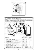
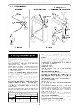
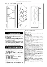
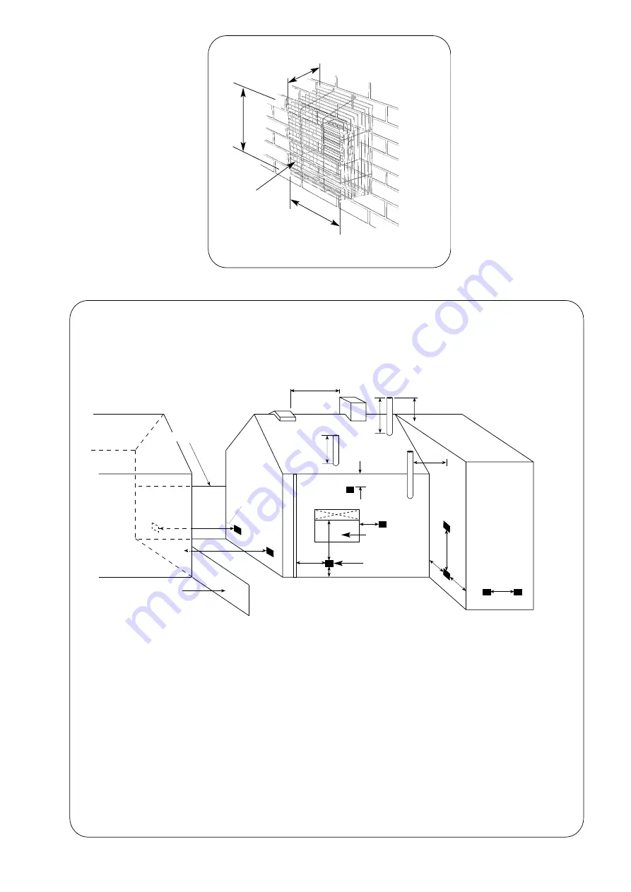
Fig. 8. Terminal guard Minimum dimensions.
265
280
280
Terminal guard.
See 7.4.5.
L
F
F
K
G
A
E
B
C.D.
J
N
O
M
H
F
Boundry
Boundry
P
M
Minimum Distance (mm)
Terminal Position
Open
Low-Level
Vertical
Flue
Discharge Balanced Flue
A
Directly below an opening, air brick, window, etc. .......................................... Not allowed
600
Not allowed
B
Horizontally to an opening, air brick, window, etc. ........................................ Not allowed
600
''
C
Below a gutter or sanitary pipe if combustible material protected. .............. Not allowed
75
''
D
Below a balcony, eaves, gutter or drainage without protection
to combustible material. ...................................................................................... Not allowed
600
''
E
From vertical sanitary pipework.. ....................................................................... Not allowed
300
''
F
From an internal or external corner or boundry along side terminal. .......... Not allowed
300
''
G
Above ground or balcony level. .......................................................................... Not allowed
300
''
H
From a surface or boundry facing the terminal. .............................................. Not allowed
600
''
J
From a terminal facing the terminal. ................................................................. Not allowed
1200
''
K
Vertically from a terminal on the same wall. ................................................... Not allowed
1500
L
Horizontally from a terminal on the same wall. .............................................. Not allowed
750
''
M Above an intersection with the roof. .................................................................
600
Not applicable 732
NFrom a vertical structure on the side of the terminal......................................
750
N
ot applicable 750
O
Above a vertical structure less than 750mm from the side of the terminal. 600
Not applicable 732
P
From a ridge terminal to a vertical structure on the roof................................
1500
Not applicable Not applicable
NOTE:
The dimensions given are for general guidance only. Other surrounding buildings or objects may affect the clearance of
combustion products. An alternative flue terminal position should be sought when there is any possibility of a nuisance being
caused by inadequate dispersal of flue products.
Terminals should be positioned so as to avoid products of combustion entering into buildings.
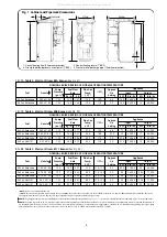
Fig. 7. Flue terminating positions for oil-fired appliances
Window
Flue
Terminal
All manuals and user guides at all-guides.com


