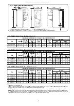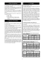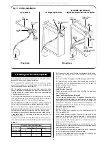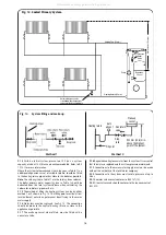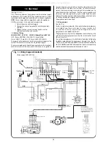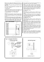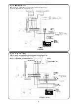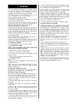
(See Figs. 14 to 19).
10.1
The wiring between the appliance and the electrical supply
shall comply with current IEE wiring regulations (and any local
regulations which apply) for fixed wiring to a stationary appliance.
NOTE:
It must be possible to completely isolate the appliance.
10.2
To gain access to the electrical terminal strip.
1. Isolate the mains electrical supply.
2. Remove the cabinet top panel by snatching squarely
upwards.
3. Release the four screws securing the cover of the
electrical control box and remove.
10.3 Mains Wiring
MAINS SUPPLY – 230V AC ~ 50HZ 5A External Fuse to BS1362.
LIVE - Brown, NEUTRAL - Blue, EARTH - Green/Yellow
Mains Cable: 0.75mm (24 x 0.20 mm) to BS6500 Table 16.
The supply to the boiler must be the only electrical supply to the
system. This ensures the safety of a single fused supply.
The mains supply cable should be connected into the terminals
marked
L
(Live),
N
(Neutral) and
E
(Earth) on the appliance
terminal strip and securely held in the cable clamp located in the
left-hand side of the electrical tray box. To secure the cable,
remove the clamp retaining screw and pull its inner body out to
allow the cable to be fed through. With the cable in position refit
the screw and fully tighten to grip the cable. Feed the cable
between the side panel and the boiler insulation jacket and route
to the connection point avoiding any hot surfaces.
The appliance must be earthed.
10.4 Programmer
(See Fig. 16a).
A plug in, colour co-ordinated, 2 channel electronic programmer
is available from Worcester Heat Systems Limited. Full
instructions covering installation and operation of the
programmer are included with the kit.
The programmer will give fully independent central heating (CH)
and hot water (HW) programmes when the switch on the rear of
the unit is set to P.
If an external programmer is to be fitted to the boiler the link plug
should be removed from the programmer terminal strip. (See Fig.
16b). The LIVE, NEUTRAL and EARTH wires should be connected to
the LIVE, NEUTRAL and EARTH terminals on the main terminal strip
and the switched lines connected to terminals 1 and 2.
10. Electrical
15
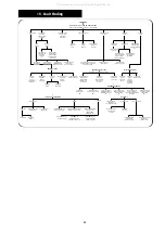
Brown
Brown
Brown
Brown
Green/Yellow
E N L
Green/Yellow
Earth
Stud
Manual reset
thermostat
Time clock
white
connecter
Post purge
black
connecter
High limit
thermostat
Control
thermostat
Mains on
neon
Lockout
neon
5 Amp.
Blue
Blue
Green/Yellow
Green/Yellow
Post Purge Unit.
For use on open flue low
level discharge models
only. (Not RS models) Unit
supplied in Flue Kit.
Yellow
Pink
Brown
Blue
Yellow
Pink
Brown
Black
Black
Red
Grey
Grey
Brown
White
White
Operating Switch
Brown
Plug in
connector
Brown
Brown
Orange
(1)
(C)
Blue
Blue
Green/Yellow
Blue
White
Grey
L N E E N 1 2 3 4 5 6
1 2 3 4 5 6
7 8 9 10
11 12 13 14 15
Mains supply 230/240V 50Hz
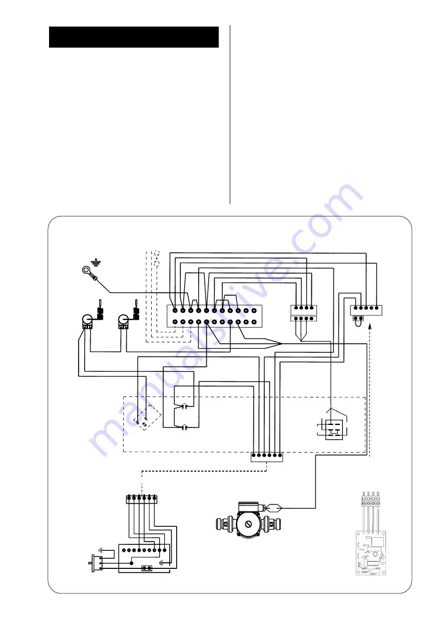
Fig. 14. Wiring Diagram (Standard).
Blue
Green/Yellow
Brown
Pump
Plug in connector
N
N
E
L
Satronic control box
Fan motor
Blue
Brown
E
Green/Yellow
Green/Yellow
Yellow
Grey
Pink
Red
Black
1 2 3 4 5 6
1 2 3 4 5 6 7
8 9
Burner Control
Grey
Brown
White
All manuals and user guides at all-guides.com


