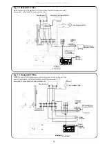
Ensure that no foreign matter is left in the system as this could
cause damage to the appliance.
Benchmark Water Treatment: For optimum performance after
installation, this boiler and its associated central heating
system should be flushed in accordance with the guidelines
given in BS7593:1992 - Treatment of water in domestic hot
water systems. Full instructions are supplied with proprietary
cleansers sold for this purpose. If an inhibitor is to be used
after flushing, it should be used in accordance with the
inhibitor manufacturers instructions.
Suitable flushing agents and inhibitors are available from Betz
Dearborn Tel: 0151 4209563 and Fernox Tel: 01799 550811.
Instructions for use are supplied with these products.
IMPORTANT: Any system cleanser must be flushed from the system
before an inhibitor is added.
12.1
Check that the electrical supply to the appliance is
switched off.
12.2
When commissioning the appliance after initial installation
follow the procedure from 12.3, otherwise remove the burner
first as described in Section 14.3.
12.3 Prepare the heating system
.
1.
After initial installation and checking for leaks, as previously
described, drain down the system sufficiently to add a flushing
agent. After flushing drain the system before filling.
2. Set the expansion vessel pressure
.
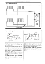
The charge pressure of the expansion as despatched is 0.5 bar,
which is equivalent to a static head of 5 metres (17ft). The
charge pressure must not be less than the static head at the
point of connection. See Figs. 12 and 13. A Schraider type valve
is fitted to the expansion vessel to allow the charge pressure to
be increased if necessary.
3.
Fill the system using one of the methods described in Section 9,
adding a suitable corrosion inhibitor in accordance with BS 7593.
4.
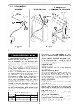
Check that the pressure relief valve operates by turning the
knob anti-clockwise until it releases. Water should be expelled
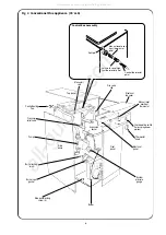
from the discharge pipe. See Fig. 1.
5.
Set the system pressure.
Fill the system until the pressure gauge shows 1.5 bar (21.5 psi) and
check for water soundness. Release water from the system until the
system design pressure is obtained,up to a maximum of 1.5 bar.
System design pressure = Static head of the system in bar + 0.3.
Note:
1 bar is equivalent to 10.2 metres (33.55 ft) of water.
Set the moveable pointer giving a permanent record of the set sys-
tem pressure.
If the pressure indicated on the pressure gauge is greater than 2.5
bar when operating at the maximum central heating temperature,
then an extra expansion vessel must be fitted to the system as close
as possible to the appliance central heating return connection. Refer
to Section 9 for further information on system capacities.
Any extra vessel must be pressurised to the same figure as the inte-
gral vessel. If the expansion vessel fails then the specified replace-
ment must be fitted.
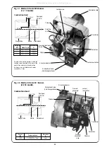
12.4 Check the Burner
1.
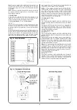
Check that the nozzle and electrode settings are correct for the
relevant burner. (See Figs. 20, 21 and 22).
2.
Check that the nozzle lies central with the combustion head hole.
3.
Check for any visible defects.
12.5 Replace the burner.
1.
Connect the flexible oil supply hose to the isolating valve bulkhead
fitting and tighten sufficiently to form a good seal. Where a double pipe
system or single pipe system with de-aerator is being used fit the
bypass plug, provided in the plastic bag on the burner, as shown in
Fig. 9 and connect the oil return flexible hose to the return pipe fitting.
2.
With the sponge O-ring gasket around the burner blast tube
insert the burner into the housing tube. Push the burner firmly for-
ward to compress the gasket and tighten the two locking screws
using a 5mm Allen key.
Note:
It is important that a good seal is made between the burner
and the boiler to prevent re-circulation of the flue gases from the
combustion chamber to the burner inlet or the room in the case of a
CF/LLD appliance.
3.
On the RS balanced flue model, feed the electrical lead back
through the hole in the burner surround housing and fit the grom-
met into the hole ensuring a seal is made.
4.
Re-connect the electrical lead plug into the control box.
12.6 Check the installation.
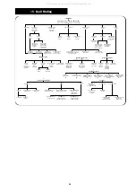
1.
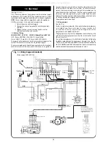
Check that the appliance is correctly wired as described in Section 10.
2.
Check the combustion chamber base insulation is positioned cor-
rectly in the bottom of the boiler.
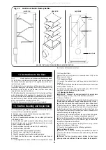
3.
Check that all baffles are correctly located and the heatshield is
correctly mounted (20-25 model only) as shown in Fig. 23.
4.
Check that the baffle retainer is correctly mounted (20-25 model
only) as shown in Fig. 23.
5.
Check that the control thermostat and auto reset high limit ther-
mostat phials are correctly located in the boiler thermostat pocket
positioned in the top front of the boiler.
6.
Check that the manual reset limit thermostat is located in the
steel pocket above the electrical box mounting bracket on the front
face of the boiler.
7.
Check that all of the air-ways to the burner are clear of any obstruction.
12.7
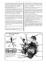
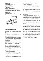
Fit a pressure gauge and manifold to the burner pump at the
point indicated in Fig. 9, or the pressure gauge port shown in Fig. 22
on the 20/25.
12.8
Turn on the electricity to the appliance.
12.9 Bleed the burner (single pipe systems only).
Release the fuel bleed port on the manifold and place a suitable
receptacle beneath. Turn on the boiler thermostat. Set the operating
switch (or programmer) to
heating and hot water
and allow the
burner to run through to lockout. Wait two minutes and reset the
burner control box. Repeat the procedure at least three times or
until a steady stream of oil, without air, is exhausted from the bleed
port. Re-lock the bleed port.
Double pipe system
A double pipe system will automatically vent the air back to the oil
tank. Turn on the boiler thermostat. Set the operating switch (or
programmer) to
heating and hot water
and allow the burner to run
through to lockout. Wait two minutes and rest the burner control
box. Repeat the procedure until the burner fires and runs in a
steady state. This may take several attempts depending on the oil
pipe length and height.
Single pipe suction lift system with de-aerator
A single pipe suction lift system with de-aerator will automatically
vent air through the de-aerator. Turn on the boiler thermostat. Set
the operating switch (or programmer) to
heating and hot water
and allow the burner to run through to lockout. Wait two minutes
and reset the burner control box. Repeat the procedure until the
burner fires and runs in a steady state.
On long oil pipe runs from the oil tank to the boiler it is recommend-
ed that the de-aerator be primed to prevent damage to the oil
pump.
To prime the the de-aerator follow the following procedure:
a)
Disconnect the flexible oil inlet hose nearest to the de-
aerator and place the end in a container of oil.
b)
Place an empty container to collect oil from the oil
inlet pipe from the de-aerator.
c)
Prime the de-aerator and reconnect the de-aerator
to the flexible oil inlet hose.
12.10
Adjust the air shutter and pump pressure to the settings rec-
ommended in Tables 2 to 4. After a pre-ignition period of approxi-
mately 15 seconds the burner should ignite. Flame sensing is car-
ried out by means of a photocell mounted in the burner body.
Should the boiler fail to establish a normal firing pattern (or should
flame failure occur during running), the absence of a flame is sensed
and the control box is monitored to a safe lockout condition and the
12. Commissioning the Appliance
20
All manuals and user guides at all-guides.com

