background image

INSTALLATION

6 720 807 912 (2015/10)

7

4.4

SIDE FLUE OPTION: CAMRAY AND HEATSLAVE

CAMRAY LEFT HAND OPTION & HEATSLAVE RIGHT HAND OPTION

[*]

The air inlet outer section is not needed for this outlet position 
and there will be one screw spare.

[**]

Camray: for the right hand flue option reduce the air inlet outer 
section by 130mm. Ensure that the cut is square and remove 
burrs after cutting.

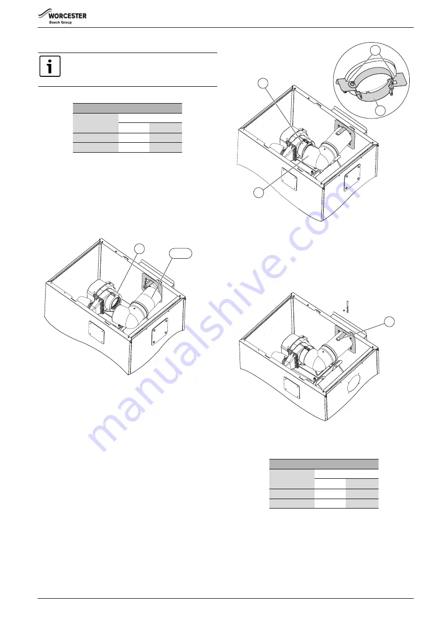
▶ Cut the flue as required, see table 3
▶ Fit the air inlet inner section [2] to the elbow.
▶ Fit the clamp [1] to the flue cowl.

Fig. 11

[1]

Flue clamp

[2]

Flue section

▶ Push the air inlet inner section through the side panel opening into the 

air box until it meets the stops [4] on the clamp assembly

▶ Centralise the inner elbow pipe within the elbow.
▶ Fit the elbow [3] onto the flue cowl.
▶ Tighten the clamp [1] onto the flue elbow.

Fig. 12

[3]

Elbow

[4]

Clamp stops

[5]

Clamp

▶ Drill through the clamp tab [6] on the mounting bracket, with the 

3.3mm drill bit, into the air inlet outer section and secure with a self-
tapping screw.

Fig. 13

[6]

Clamp tab

CAMRAY RIGHT HAND AND HEATSLAVE LEFT HAND OPTION

[*]

The air inlet outer section is not needed for this outlet position 
and there will be one screw spare.

[**]

Camray: for the right hand flue option reduce the air inlet outer 
section by 130mm. Ensure that the cut is square and remove 
burrs after cutting.

▶ Cut the flue as required, see table 4
▶ Fit the air inlet inner section [2] to the elbow.
▶ Fit the clamp [1] to the flue cowl.

To use the right hand or left hand flue options a 90° 
swept flue elbow is required (part no. 7 716 190 034)
Lightly grease the 90° flue elbow seals with the solvent 
free grease supplied.

80mmØ  flue pipe length L in mm

Flue outlet

Boiler

Camray

Heatslave

Right hand

265**

230*

Left hand

230*

345

Table 3 Flue pipe lengths

6720807912-11.1Wo

1

2a

&

2b

80mmØ  flue pipe length L in mm

Flue outlet

Boiler

Camray

Heatslave

Right hand

265**

230*

Left hand

230*

345

Table 4 Flue pipe lengths

6720807912-12.1Wo

1

3

4

5

6720807912-13.1Wo

3.3mmØ

6

Summary of Contents for Worcester Greenstar Oilfit External

Page 1: ...ONS LOW LEVEL HORIZONTAL BALANCED FLUE GREENSTAR OILFIT FLUE EXTERNAL 6720807912 00 2Wo THIS MANUAL COVERS FLUE INSTALLATION FOR THE CAMRAY DANESMOOR 2013 AND BOTH VERSIONS OF HEATSLAVE BOILERS HEATSLAVE AND HEATSLAVE II 6 720 807 912 2015 10 ...

Page 2: ...Discharge Flue options 4 4 Installation 5 4 1 Balanced Low level Discharge Flue 5 4 1 1 Flue Components 5 4 2 Rear flue options all models 5 4 3 Side flue option Danesmoor 2013 and Heatslave II 6 4 4 Side flue option Camray and Heatslave 7 4 5 All flue options final assembly 8 4 6 Terminal guard 9 Heatslave and Heatslave II For Heatslave side flue option refer to section 4 4 on page 7 For Heatslav...

Page 3: ...he building It is law that all controlled services for buildings must comply with building regulations You must be able to satisfy your Local Authority Building Control Body LABC that the work carried out concerning the installation and commissioning of the heating appliances has been carried out to a satisfactory standard OFTEC operate a competent persons scheme and registered installers are able...

Page 4: ...g 3 Flue outlet options A Left hand flue outlet using items 1 2 3 from figure 4 B Rear flue outlet using items 1 3 from figure 4 C Right hand flue outlet using items 1 2 3 from figure 4 Fig 4 Flue components 1 External horizontal flue kit Part number 7 716 190 084 2 80 125mm 90 elbow kit Swept Part number 7 716 190 034 3 Terminal guard Part number 7 716 190 050 6720807912 01 3Wo 1 2 3 4 5 6 7 8 9 ...

Page 5: ...scopic inner section 3 Telescopic outer section 4 Clamp stops 5 Clamp assembly Drill through the two sections of the flue inlet 2 3 with the 3 3mm drill bit and secure the two sections with the self tapping screw Drill through the tab 6 with the 3 3mm drill bit into the flue inlet outer section 3 and secure with the self tapping screw Fig 7 Drilling detail 2 Telescopic inner section 3 Telescopic o...

Page 6: ...e side panel opening into the air box until it meets the stops 4 on the clamp assembly Centralise the inner elbow pipe within the elbow Fit the elbow 3 onto the flue cowl Tighten the clamp 1 onto the flue elbow Fig 9 3 Elbow 4 Clamp stops 5 Clamp Drill through the tab 6 on the mounting bracket with the 3 3mm drill bit into the air inlet outer section and secure with a self tapping screw Fig 10 Tab...

Page 7: ... bracket with the 3 3mm drill bit into the air inlet outer section and secure with a self tapping screw Fig 13 6 Clamp tab CAMRAY RIGHT HAND AND HEATSLAVE LEFT HAND OPTION The air inlet outer section is not needed for this outlet position and there will be one screw spare Camray for the right hand flue option reduce the air inlet outer section by 130mm Ensure that the cut is square and remove burr...

Page 8: ...and secure with a self tapping screw Fig 16 Tab detail 4 5 ALL FLUE OPTIONS FINAL ASSEMBLY Lightly grease the flue pipe seal with the solvent free grease supplied Remove the screw from the clamp bracket 1 and open the clamp Insert the terminal 3 fully into the 80mmØ flue pipe Passthefluepipe 2 throughtheclampbracket 1 andpushintothe flue cowl or elbow Fig 17 Final assembly 1 Clamp bracket 2 Flue p...

Page 9: ... 2015 10 9 4 6 TERMINAL GUARD To fit the terminal guard 1 not supplied Hold the terminal guard 1 in place and secure with the four screws 2 removed from the air box earlier Fig 19 1 Terminal guard 2 Screws 6720807912 19 1Wo 1 2 ...

Page 10: ...6 720 807 912 2015 10 10 NOTES ...

Page 11: ...6 720 807 912 2015 10 11 ...

Page 12: ... Worcester Bosch Group is a brand name of Bosch Thermotechnology Ltd worcester bosch co uk 6 720 807 912 2015 10 WORCESTER BOSCH GROUP TECHNICAL SUPPORT 0844 892 3366 APPOINTMENTS 0844 892 3000 SPARES 01905 752571 LITERATURE 0844 892 9800 TRAINING 01905 752526 SALES 01905 752640 ...

Reviews: