WIRED REMOTE CONTROLLER INSTALLATION MANUAL
1.
SAFETY PRECAUTIONS
• Read the safety precautions carefully before installing the unit.
• Stated below is important safety information.
• Once test operation has been successfully completed, this manual
must be left with the user.
WARNING
Failure to observe a warning may result in serious injury.
CAUTION
Failure to observe a caution may result in injury or damage to the
equipment.
WARNING
Ensure only trained and qualified personnel install or repair this
controller.
Failure to follow the instructions set out in this manual, may result in
injury or equipment damage.
CAUTION
The correct cable must be used for this controller.
All wiring must be completed in accordance with the national wiring
regulations.
The controller must be installed in a suitable location.
2.
OTHER PRECAUTIONS
Installation Location
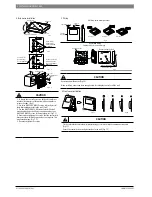
Do not install the controller in direct sunlight, near heat sources,
where steam is present or any other location which may affect the
controller. Failure to follow this instruction may result in product
failure.
Preparation before installation
1. Ensure the following fittings are supplied within the package
contents. If any parts are missing, contact your service agent to obtain
a new one.
No.
Name
Qty.
Description
1
Wire controller
1
2
Screws
3
GB950-86 M4X20
(For Mounting on the Wall)
3
Screws
2
M4X25 GB823-88
(For Mounting on the
Electrical Switch Box)
4
Installation Manual
1
5
Owner’s Manual
1
6
Wall Plug
3
For mounting the unit to the
wall
7
Plastic screw
2
For fixing electrician box
8
Communication cable to
receive information
1
To connect to the receiving
board
9
Communication cable
to connect to the wired
controller
1 (If needed) to connect to the
main control panel
10
Communication cable for
controller signal
1 To connect to the indoor unit
2. Prepare the following assemblies on the site.
No.
Name
Qty.
Specification
Description
1
4-core shielded
cable
1
0.5mm2x4
The longest
is 15m
2
86 Electrician
box
1
3
Conduit/
Containment
1
Installation of wire controller.
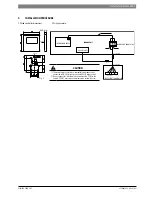
1. Please refer to Indoor Unit Installation Manual for connective wiring
between the Wired Remote Controller and the Indoor Unit.
2. The wiring to the controller is low voltage and must never be
connected to a 230v mains electrical supply.
3. The shielded layer of the shielded cable must be grounded to avoid
communication errors.
4. Any connections to the communication cable must be done
correctly to a void communication errors.
5. Never use a megger test to check the installation. This will cause
serious damage.
2 | SAFETY PRECAUTIONS
6720863624 (2016/04)
CLIMATE 5000 VRF

