19
3.7 Bridged Mono/Dual Mono Switching
The Stereo/Mono Switch (S1) on the Input Board is a three-position switch used to select Normal Stereo,
Bridged Mono or Dual Mono operation. In the Bridged Mono position, it connects CH 1 in parallel with the
CH 2 input, but inverts the signal to CH 1. The CH 1 input connection becomes disabled. The speaker
output signals are identical except CH 1 is 180 degrees out of phase. In this way, a single speaker can be
connected between the two “+” speaker terminals and receive twice the voltage as a single channel.
When connected in this way, each channel “sees” one-half the impedance of the speaker that is
connected between them. If an 8 ohm speaker is used, each channel will see a 4 ohm load. Each channel
can still be independently controlled with its own level control so it is important that both level controls
be set to the same position for a balanced output.
The result is twice the rated power (per channel)
into twice the rated impedance.
When S1 is switched to the Dual Mono position, CH 1 is connected in parallel with the CH 2 input, but in
phase. The CH 1 input connection becomes disabled. This allows both channels to be driven with the
same signal without the use of special patch cords. Each channel can still be independently controlled
with its own level control.
3.8 Parallel Mono
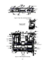
To operate in Parallel Mono mode, leave S1 in the Normal Stereo position. Removing jumpers JP201 and
JP203 will disconnect the CH 2 predrivers from the output stage. Installing jumpers JP102, JP104, JP202
and JP204 will connect the CH 1 predrivers to the CH 2 output stage. In this way, both channels will
operate at exactly the same level, and will be controlled by the CH 1 level control.
In addition, removing JP1 will prevent the CH 2 clip LED from activating, and installing a 16 ga. jumper
wire between WL100 and WL200 on the Output Board will tie both amplifier outputs together before the
relays.
When operating in parallel mono, either of the speaker output terminals (CH 1 or CH 2) can be used since
they both have exactly the same signal present. When a speaker is connected to the output terminals it
can be driven with twice the current capacity of a single channel. The result is twice the rated power (per
channel) into half the rated impedance.
Summary of Contents for 1800-V
Page 7: ...Figure 3 502A EQ Card HF Only Response Figure 4 502A EQ Card Full Frequency Response 7...
Page 8: ...Figure 6 802 EQ Card HF Only Response Figure 5 502B EQ Card Response 8...
Page 9: ...Figure 7 802 EQ Card Full Range Response 9...
Page 69: ...402 Equalizer Card Schematic 69...
Page 70: ...502A Equalizer Card Schematic 70...
Page 71: ...502B Equalizer Card Schematic 71...


