31
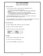
3. 502B Equalizer Curve
Use the following test set-up parameters when measuring the 502B card's response outputs:
A. Apply a signal of 80 Hz at 1 Vrms and adjust the amplifier's output to 6 Vrms.
B. Reference a dB meter to the output.
C. Measure the response according to the following chart.
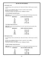
4. 802 Equalizer Curve
Use the following test set-up parameters when measuring Full Range or High Frequency response
outputs:
A. Apply a signal of 700 Hz at 1 Vrms and adjust the amplifier's output to 6 Vrms.
B. Reference a dB meter to the output.
C. Measure the response according to the charts in Sections 4.1 and 4.2.
2.2 502A High Frequency Response
IMPORTANT: Set the Input Module's S2 switch to the HF Only (High Frequency) position before
beginning this test.
4.1 802 Full Range Frequency Response
IMPORTANT: Set the Input Module's S2 switch to the Full Bandwidth (Full Range) position before
beginning this test.
FREQUENCY
OUTPUT SPECIFICATION (dbr)
40
-28.5
±
2.0 dB
140
+3.7
±
1.5 dB
600
0.0
2200
+3.5
±
1.5 dB
5000
+12.5
±
1.5 dB
15000
+19.0
±
1.5 dB
FREQUENCY
OUTPUT SPECIFICATION (dbr)
40
-6.2
±
2.0 dB
80
0.0
100
+1.3
±
1.0 dB
300
-17.5
±
2.0 dB
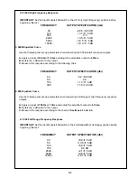
FREQUENCY
OUTPUT SPECIFICATION (dbr)
40
+8.0
±
1.5 dB
55
+13.5
±
1.5 dB
140
+6.6
±
1.5 dB
700
0.0 dB
2500
+2.1
±
1.5 dB
6000
+9.6
±
1.5 dB
14500
+16.7
±
1.5 dB
Summary of Contents for 1800-V
Page 7: ...Figure 3 502A EQ Card HF Only Response Figure 4 502A EQ Card Full Frequency Response 7...
Page 8: ...Figure 6 802 EQ Card HF Only Response Figure 5 502B EQ Card Response 8...
Page 9: ...Figure 7 802 EQ Card Full Range Response 9...
Page 69: ...402 Equalizer Card Schematic 69...
Page 70: ...502A Equalizer Card Schematic 70...
Page 71: ...502B Equalizer Card Schematic 71...

