Optional 70/100V transformer accessory part list and installation
Notes:
1. To be used with Model 203
®
pro gray variation only.
2. To be used with Model 203 artic white variation only.
Transformer accessory installation
Note:
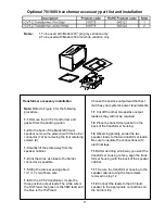
Refer to Figure 6 for the following
procedure.
1.1
Remove the CVT-2 transformer and
gasket from the packing carton.
1.2
On the back of the Model 203 loud-
speaker, remove the plate (9) with the barrier
connector (10) by removing the four retaining
screws (2).
1.3
Gently lift the plate away from the
speaker cabinet.
1.4
Cut the wires as close to the barrier
connector as possible.
1.5
Strip the wires exposing about
1/2” (1.7 cm) of bare wire.
1.6
On the CVT-2 transformer, locate the
three positive output leads. The white wire is
the 19W lead, the green is the 38W lead and
the blue is the 75W lead.
Choose the positive output lead that best
matches your system’s power requirements.
1.7
Cut off the other two positive output
leads as they will not be required.
1.8
Place the transformer gasket on the
back of the transformer housing.
1.9
Observing polarity, solder the two
speaker leads to the two transformer leads.
Be sure to insulate the connections with
electrical tape.
1.10
After deciding which way you want the
transformer housing to face, align the trans-
former housing with the back of the speaker
cabinet.
1.11
Secure the transformer housing to the
speaker cabinet using the four screws
removed in step 1.2.
1.12
Connect the leads to the 203 loud-
speaker to the appropriate connections on
the barrier strip.
11


