background image

SERVICE MANUAL REVISION HISTORY

Date Revision 

Level 

Description of Change 

Change Driven By Pages 

Affected 

8/97 

00 

Document release revision 00 

Service manual release 

All 

3/02 

00 

Part numbers for PTC1 and 
PTC2 changed.  
 
Part number for the CTV-2 
transformer accessory changed 

Part number change 


Part number change 


11 

04/06 

01 

Added RoHS part numbers 


Supplement 193625-S1 and 
193625-S2 information added. 

This product is now 

built with RoHS 

compliant parts. 


PTC1, PTC2, CVT-2 

part numbers updated.  

8,9,10,11 


8,11 

05/10 

02 

New driver part number 

Part number change 


12

Summary of Contents for L-Bracket 203

Page 1: ...MODEL 203 LOUDSPEAKER 2010 Bose Corporation Reference Number 193625 SM Rev 02 Service Manual ...

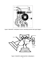
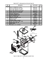
Page 2: ...bly Assembly procedures 3 4 Test Procedures 5 Figure 1 Model 203 Loudspeaker test setup diagram 5 Figure 2 Model 203 Loudspeaker Crossover Assembly topside and etch layout diagram 6 Figure 3 Model 203 Loudspeaker Driver wiring diagram 6 Figure 4 Model 203 Loudspeaker Crossover Assembly schematic diagram 7 Model 203 Loudspeaker Crossover Assembly part list per figure 5 8 Figure 5 Model 203 Loudspea...

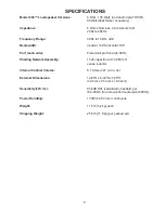
Page 3: ...d slot port tuned to 60 Hz Shading Network Assembly 10uF capacitor with 0 065 mH series inductor Internal Cabinet Volume 5 7 Liters 347 cu in net External Dimensions 12 83 L x 8 43 D x 7 25 H 32 6cm x 21 4cm x 18 42cm Sensitivity 1W 1m 83 8dB SPL calculated freefield per IEC 268 5 for octave band centered at 400Hz Power Handling 100W 24 5 Vrms continuous Weight 11 5 lb 5 2 kg each Shipping Weight ...

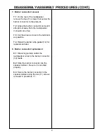
Page 4: ...r code and cut the wires as close to the terminals as possible 4 Driver replacement 4 1 Observing polarity solder the wires from the crossover assembly 5 to the driver 3 terminals 4 2 Orient the driver correctly into the cabinet and secure it using the screws 2 removed in procedure 3 2 4 3 Replace the grille 1 using procedure 2 5 Crossover Assembly removal 5 1 Remove the grille 1 and angled driver...

Page 5: ...eaker It should come free 7 3 Cut the wires as close to the terminals as possible 7 4 Retain the barrier strip gasket 12 for replacement later 8 Barrier connector replacement 8 1 Observing polarity solder the loudspeaker wires to the barrier connector 10 leads 8 2 Slide the barrier connector into the speaker cabinet Be sure it is oriented properly 8 3 Secure the barrier connector to the speaker ca...

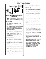
Page 6: ...g noise There shall not be any buzzes or rattles from the internal connecting wires or components Redress any buzzing wires Power Amplifier Frequency Generator Loudspeaker DMM Figure 1 Model 203 Loudspeaker test setup diagram Note Refer to Figure 3 Model 203 driver wiring diagram for the following procedure 1 Phase test 1 1 Remove the speaker grille using procedure 1 1 2 Observing polarity apply a...

Page 7: ... Figure 3 Model 203 Loudspeaker Driver wiring diagram Figure 2 Model 203 Loudspeaker Crossover Assembly topside and etch layout diagram BLUE BLACK GREEN YELLOW _ BARRIER STRIP PCB D R I V E R DRIVER RED ...

Page 8: ...udspeaker Crossover Assembly schematic diagram TO TO DRIVER DRIVER BLACK IN IN FRONT ANGLE BLUE BLUE YELLOW GREEN 1 W6 PTC2 0 4A 1 3 OHM RXE040 1 W1 L1 65uH C1 10 50V DS2 DS1 PTC1 0 90A 0 5 OHM RXE 090 1 W5 1 W4 1 W2 1 W3 RED ...

Page 9: ...n Part Number Qty 1 C1 Cap El BP 85 50V 20 10 uF 290391 100 1 2 PTC2 Polyswitch 60V 4mm 190348 040 1 3 PTC1 Polyswitch 50V 4mm 190348 090 1 4 Tape Foil w liner 134636 1 5 DS1 DS2 Lamp 2 5 24Vdc Mini 132111 2 6 PCB Bare Board 203 Crossover 291226 001 1 7 L1 Inductor 65 uH 11 Ohm Ferrite 189799 1 8 Screw Machine 4 40x1 Pan Xrec 103146 16 1 9 Washer Flat 141 5 108258 05 1 10 Nut Hex 4 40 103234 440 1...

Page 10: ... Arctic White 187223 011 187223 021 187223 012 187223 022 1 2 Screw Tapp 8 11x75 Pan Xrc Sq 289388 012 10 3 Driver Assembly 4 5 Model 203 187233 002 2 4 Grommet Grille Socket 176068 4 5 Crossover Assembly 203 291034 001 1 6 Insert Threaded Ext Intl 121690 4 7 Nut Lock Flange M8 121691 4 8 Washer Lock 326 5 16 Intl T 121692 31 4 9 Plate Arctic White Plate Pro Gray 190649 001 190649 003 1 10 Connect...

Page 11: ...1 2 3 4 3 5 10 Item Number Description Part Number Qty 1 Manual Owner s Model 203 191913 1 2 Bracket 203 Arctic White Bracket 203 Pro Grey 190650 001 190650 003 2 2 3 Packing End Cap Model 203 187243 001 2 4 Bag Poly 13 5x33 5x13x3 mil 114522 2 5 Carton RSC 300PM 291034 001 1 Hardware Kit Bracket 290316 001 1 ...

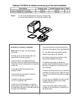
Page 12: ...he CVT 2 transformer locate the three positive output leads The white wire is the 19W lead the green is the 38W lead and the blue is the 75W lead Choose the positive output lead that best matches your system s power requirements 1 7 Cut off the other two positive output leads as they will not be required 1 8 Place the transformer gasket on the back of the transformer housing 1 9 Observing polarity...

Page 13: ...rt numbers for PTC1 and PTC2 changed Part number for the CTV 2 transformer accessory changed Part number change Part number change 8 11 04 06 01 Added RoHS part numbers Supplement 193625 S1 and 193625 S2 information added This product is now built with RoHS compliant parts PTC1 PTC2 CVT 2 part numbers updated 8 9 10 11 8 11 05 10 02 New driver part number Part number change 9 12 ...

Page 14: ...FICATIONS AND FEATURES SUBJECT TO CHANGE WITHOUT NOTICE P N 193625 SM REV 02 05 10 FOR TECHNICAL ASSISTANCE OR PART ORDERS CALL 1 800 367 4008 Bose Corporation The Mountain Framingham Massachusetts USA 01701 ...

Reviews: