background image

English 

Installation and Safety Guidelines 

Page 9

pro.Bose.com

Installation

Array Rigging

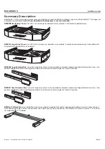
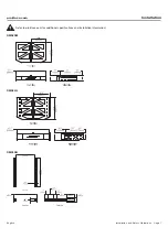
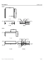
Each RoomMatch™ full-range module includes integrated side-plate array rigging hardware. The rigging system is designed to 
allow fast construction of typical fixed-installation arrays of up to 8 modules, while maintaining a 10:1 Safety Factor. Additionally, the 
RoomMatch™ RMS215 subwoofer is designed to integrate with full-range modules in arrays when the optional RMSFLY accessory part 
is installed on the subwoofer. To connect RoomMatch™ modules for suspended arrays, the following steps are recommended:

Note:

 Prior installation of field wiring and a safety-rated suspension system, e.g. chain-hoist motors or wire-rope slings, is assumed. 

Motors may be used as a permanent suspension method or to temporarily elevate an array to final position for attachment to conven-
tional rigging hardware.

Note: All lifting operations require two individuals positioned on each side of the loudspeaker.

Before You Begin – Recommended Tools

(2) 15 mm sockets and socket wrenches

 (module to module bolts: M10 x 30 mm)

(2) 17 mm sockets and socket wrenches 

(if using frame extender bars)

(2) 17 mm combination wrenches

 (for extender bar bolts)

(2) 5/16-inch Aligning Punch

 (optional; to aid bolt alignment)

Preparing Modules for Installation

Step 1

Retain orange-color Temporary Installation Handles included in package. Remove the RoomMatch™ modules from the shipping 
cartons, remove packing materials, and place the loudspeakers on the floor beneath planned suspension point.

CAUTION:

 Do not place loudspeakers resting on grills.

CAUTION:

 Place loudspeakers on a flat surface; verify loudspeaker weight is not supported by driver adapters.

Step 2

Locate the temporary installation handles and thread onto each module (see module instruction sheet).

Step 3

Remove four (4) M10 bolts from top of rigging side plates for each module (2 per side). 

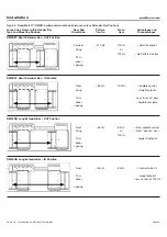
Section A: Small or Large Array Frame (without Extender Bars)

1.

Use

RoomMatch

Array Suspension Angle Calculator

 software to determine the hole positions on the array frames for required 

aiming angles and confirm array does not exceed load limits of frame. 
(You may also contact your local Bose Technical Support or Field Engineer for this information.)

2.

Place array frame directly under the chain motors positioned for intended array location.

3.

Attach 5/8 –inch forged steel frame shackles to array frame in hole positions determined by aiming software. 

4.

Lower chain motors and attach to shackles installed on array frame. 

5.

Raise array frame to height slightly greater than that of the 1st module (upper most) to be installed. 

Note: subwoofer modules should always be placed in the upper-most array positions. 
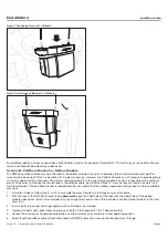
6.

With 1 person per side, place the 1st module directly under the suspended array frame. See Figure 1.

7.

Lower the array frame onto the 1st module, guiding the pins of the temporary handles into the slots of the frame.

8.

Using handles, pull the module forward to align the bolt holes of the module and frame. (Note: it may be helpful to use an alignment 
punch tool in the rear holes and then thread the bolts in the front holes first.) 

9.

Insert 4 bolts (2 per side) and finger tighten each until all bolts are installed.

10. Tighten all 4 bolts with socket tool using torque of 35 to 40 foot-pounds (47 to 54 Newton-meters).

11. Raise array frame to height slightly above that of 2nd module. 

12. Position 2nd module directly under array.

13. With 1 person per side, lift the 2nd module and guide the temporary handle pins into the alignment slots of the 1st (top) module 

side plates. See Figure 2. 

14. Holding the handles of the 1st (top) module stationary, pull forward on the handles of the 2nd (bottom) module to align the bolt 

holes of both modules. 

15. Insert 4 bolts (2 per side) and finger tighten each until all bolts are installed.

16. Tighten all 4 bolts with socket tool using torque of 35 to 40 foot-pounds (47 to 54 Newton-meters).

17. Remove temporary installation handles from top module. Handles in module just installed should remain for now.

18. Repeat steps 11 – 16 for to install additional modules in the array. Do not exceed load limits of frame. 

19. Remove any remaining temporary installation handles before elevating array to final height. 

20. Connect field wiring, test loudspeaker operation, and then elevate array assembly to final operating position.

Summary of Contents for RoomMatch RMAFLG

Page 1: ...atch Array Rigging Frames and Accessories Installation and Safety Guidelines Instrucciones de instalación y de seguridad Installation et instructions de sécurité Installations und Sicherheitshinweise RMS215 ...

Page 2: ...cation We recommend Bose mounting accessories when available A licensed professional engineer must review the design and fabrication of any custom mounting hardware 3 Bose RoomMatch array module loudspeakers feature an integrated side plate rigging system designed to facilitate loudspeaker array mounting by professional installers Module to module connections should be made using only the integrat...

Page 3: ...erá revisar el diseño y la fabricación de cualquier accesorio de montaje personalizado 3 El conjunto de altavoces modulares Bose RoomMatch incorpora un sistema integrado de instalación mediante placa lateral diseñado para facilitar el montaje del conjunto de altavoces a los instaladores profesionales Las conexiones entre módulos deberán realizarse utilizando sólo las placas laterales de instalació...

Page 4: ...sionnel qualifié la conception et la fabrication des accessoires de montage sur mesure 3 Le module d enceintes Array Bose RoomMatch est doté d un système de fixation par plaque latérale intégré destiné à en faciliter le montage par un installateur professionnel La connexion entre deux modules doit être réalisée uniquement à l aide des plaques latérales intégrées et des attaches M10 fournies Ne PAS u...

Page 5: ...se RoomMatch Array Modullautsprecher verfügen über ein integriertes Seitenplattenverankerungssystem das die Montage des Lautsprecher Arrays durch fachkundige Monteure erleichtern soll Verbindungen zwischen den Modulen dürfen nur mithilfe der integrierten Verankerungsseitenplatten und den mitgelieferten M10 Befestigungselementen vorgenommen werden Verwenden Sie KEINE Befestigungselemente mit einem ...

Page 6: ...xtender Bars see below RMXLNG Long Extender Bars Use with Large Array Frame to accommodate subwoofer module mounting behind primary array Also provides additional shackle mounting pickup points to allow more extreme angles for 2 point mounting RMXSRT Short Extender Bars Use with Large Array Frame to accommodate subwoofer module mounting behind primary array Also provides additional shackle mountin...

Page 7: ...English Installation and Safety Guidelines Page 7 pro Bose com Installation Refer to pro Bose com for additional specifications and installation information RMAFSM RMAFLG RMXLNG ...

Page 8: ...Page 8 Installation and Safety Guidelines English Installation pro Bose com RMXSRT RMPULL ...

Page 9: ... required aiming angles and confirm array does not exceed load limits of frame You may also contact your local Bose Technical Support or Field Engineer for this information 2 Place array frame directly under the chain motors positioned for intended array location 3 Attach 5 8 inch forged steel frame shackles to array frame in hole positions determined by aiming software 4 Lower chain motors and att...

Page 10: ... the tension load in the pullback cable Use the RoomMatch Array Suspension Angle Calculator soft ware to determine if the pull back bracket is required and then to confirm that the pullback angle and working load is within acceptable safe limits 1 In Section A above follow steps 1 to 19 to assemble the array modules on the large or small array frame 2 With the tabs of the RMPULL bracket facing down...

Page 11: ...s 47 to 54 Newton meters 5 If only 1 module is to be suspended using the RMPULL bracket skip to step number 12 6 If 2 modules are to be suspended connect shackles to the 4 mounting holes of the bracket and elevate module and bar assembly to height slightly above that of 2nd module to be suspended 7 Place the 2nd RoomMatch array module on directly under the 1st module assembly 8 With 1 person per s...

Page 12: ... labels 3 Locate the Large Array Frame and position on the ground near the intended suspension point 4 From the rear of the Large Array Frame insert the bar marked L into the channel on the right side of the array frame Note the double rows of mounting holes should be facing upward 5 Align the bolt holes with the intended position marker OUT or IN of the bar 6 Insert 4 bolts 2 per side and finger t...

Page 13: ...0 Raise array frame to height slightly greater than that of the subwoofer module 11 Install RMSFLY side plate kit to RMS215 subwoofer modules following steps included with RMSFLY kit 12 Position front RMS215 module directly under Large Array Frame 13 Position rear RMS215 module directly under mounting hole tabs of Extender Bars 14 Lower the Array Frame Extender Bar assembly to align the front hole...

Page 14: ...osition Forward 120 Hz 100 Hz Small Footprint Firing or 120 Hz No Pattern Control 0 7 m driver spacing RMXSRT Short Extender Bar IN Position Rear 85 Hz 100 Hz Audible control Firing Small footprint 1 0 m Less punchy bass driver Audible rear lobe spacing RMXLNG Long Extender Bar OUT Position Front 85 Hz 80 Hz Best audible control Firing or Best punchy bass 100 Hz 1 0 m Largest footprint driver spac...

Page 15: ...ce Bose S A S 12 rue de Temara 78100 St Germain en Laye France 01 30616363 Germany Bose GmbH Max Planck Strasse 36D 61381 Friedrichsdorf Deutschland 06172 7104 0 Hong Kong Bose Limited Suites 2101 2105 Tower One Times Square 1 Matheson Street Causeway Bay Hong Kong 852 2123 9000 India Bose Corporation India Private Limited 4th Floor Shriram Bhartiya Kala Kendra 1 Copernicus Marg New Delhi 110001 I...

Page 16: ... 2011 Bose Corporation All rights reserved The Mountain Framingham MA 01701 9168 USA www pro Bose com All trademarks are the property of their respective owners AM346847 Rev 00 ...

Reviews: