background image


69

5.4  Audio Driver Installation 

5.4.1 Win 95/98 

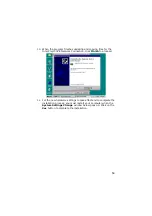
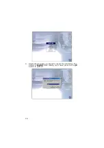
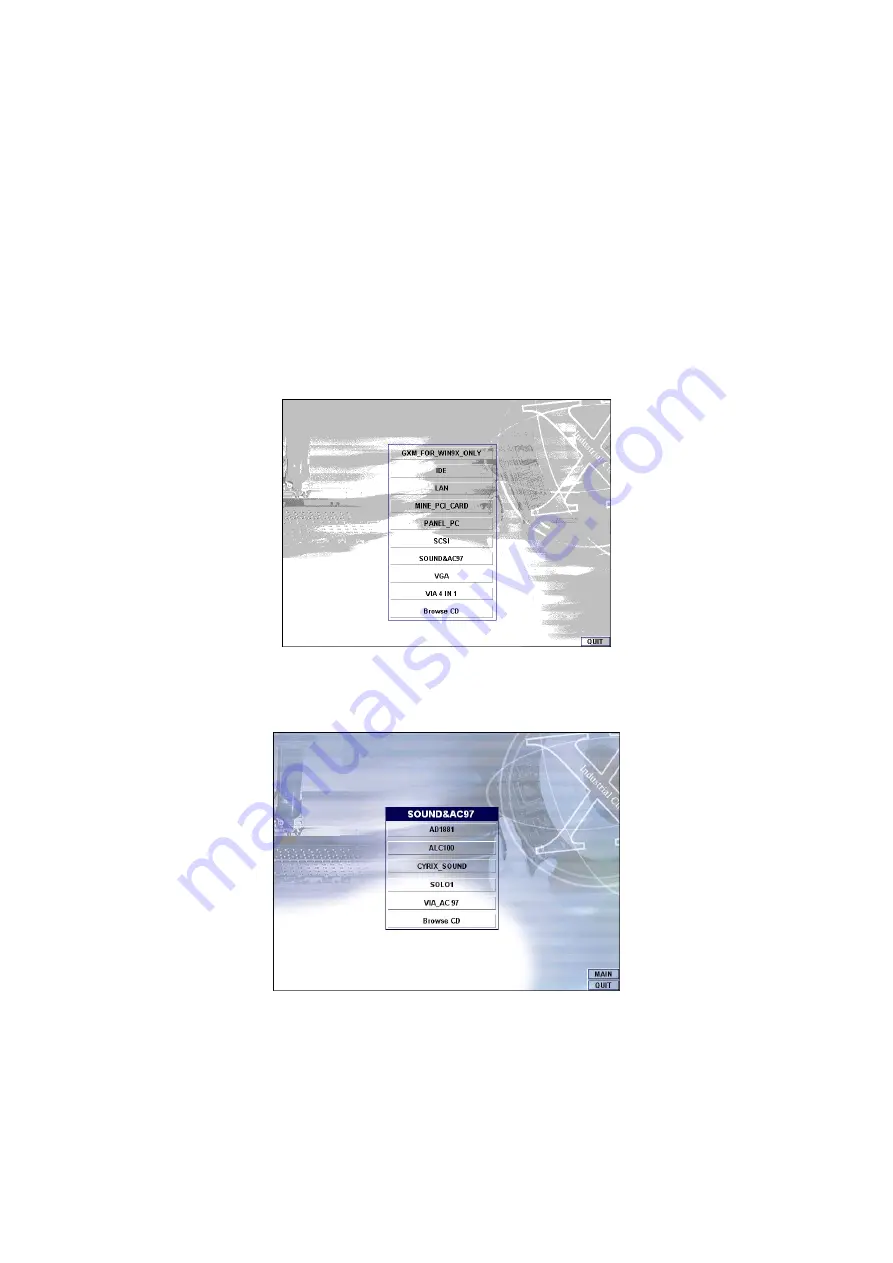
1.  After loading the Utility CD-ROM, the program automatically runs 

the utility. Press 

Enter

 to proceed installing. When the main 

utilities window pops on the screen, select 

SOUND&AC7


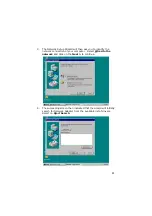
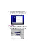
2.  The succeeding screen will then show you the 

SOUND&AC97


main menu. Select on 

ALC 100

 to continue installation. When 

the ALC100 dialog box appears, pick on 

WIN98_ME

 and it will 

take you to the ALC 100 menu. Refer to the following screen 

shots for a graphical description of this step. 


Summary of Contents for HS-4700

Page 1: ...HS 4700 PGA 478 Pentium 4 Industrial Embedded Engine Board All in One CRT Panel PCI Slot ATA 33 66 100 Dual LAN Audio 4COM IrDA USB H W Monitor...

Page 2: ...tly is prohibited unless granted permission by BOSER Technology Co Ltd BOSER Technology Co Ltd reserves the right to change or improve the contents of this document without due notice BOSER Technology...

Page 3: ...nector List 9 3 5 Configuring the CPU 10 3 6 System Memory 10 3 7 VGA Controller 10 3 8 SMI Signal Input Switch 12 3 9 PCI E IDE Drive Connector 12 3 10 Floppy Disk Drive Connector 14 3 11 Serial Port...

Page 4: ...l Setup 33 4 10 Hardware Monitor Setup 34 4 11 Auto Detect Hard Disks 35 4 12 Change Supervisor User Password 36 4 13 Auto Configuration with Optimal Settings 37 4 14 Auto Configuration with Fail Safe...

Page 5: ...strap available from most electronic component stores when handling boards and components Fasten the ALLIGATOR clip of the strap to the end of the shielded wire lead from a grounded object Please wear...

Page 6: ...This Page is intentionally left blank...

Page 7: ...rchitecture allows the HS 4700 to support data transfers of 33 66 or 100MB sec to each IDE drive connection Designed with the Intel 82845 core logic chipset the board supports all PGA 478 Pentium 4 CP...

Page 8: ...01BA system chipset Three DIMM sockets with a max capacity of 1 5GB Winbond W83627 super I O chipset Fast PCI ATA 33 66 100 IDE controller Four RS 232 serial ports C T 69030 CRT Panel display controll...

Page 9: ...Supports up to two floppy disk drives Parallel One enhanced bi directional parallel port supporting SPP ECP EPP LAN Intel 82559 and one Intel 82562 10 100 Based LAN Audio AC97 3D audio controller Seri...

Page 10: ...4 1 3 Board Dimensions...

Page 11: ...and exercise extreme care to prevent damage to the board from static electricity Integrated circuits will sometimes come out of their sockets during shipment Examine all integrated circuits particula...

Page 12: ...the delivery package intact and store them in a safe dry place for any unforeseen event requiring the return shipment of the product In case you discover any missing and or damaged items from the lis...

Page 13: ...t settings and CMOS setup correctly Refer to the sections on this chapter for the default settings of each jumper Set JP3 1 2 2 Go through the connections of all external devices and make sure that th...

Page 14: ...8 3 2 Board Layout...

Page 15: ...Off Switch CN4 HDD LED Connector CN6 External Speaker Connector CN7 Reset Connector CN8 Green LED Connector CN11 50 pin Panel Connector CN12 MIC In Audio Out Connector CN13 LAN2 Connector CN14 LAN1 C...

Page 16: ...e DIMM sockets at locations DM1 DM2 and DM3 The maximum capacity of the onboard memory is 1 5GB 3 7 VGA Controller The onboard C T 69030 with 4MB memory supporting CRT Panel displays up to 1600 x 1200...

Page 17: ...FPSCLK 36 FLM 37 M 38 LP 39 GND 40 ENABKL 41 P26 42 P27 43 P28 44 P29 45 P30 46 P31 47 P32 48 P33 49 P34 50 P35 1 2 50 49 12V GND 3 3V 5V ENAVEE P0 P2 P4 P6 P8 P10 P12 P14 P16 P18 P20 12V GND ENAVDD G...

Page 18: ..._SMI 2 GND 1 2 3 9 PCI E IDE Drive Connector IDE1 and IDE2 are standard 40 pin connector daisy chain driver connector serves the PCI E IDE drive provisions onboard the HS 4700 A maximum of four ATA 33...

Page 19: ...0 PDD11 PDD15 N C GND GND GND 470 Pull GND GND N C P66DET PDD12 PDD13 PDD14 PDA2 PDCS 3 GND 1 2 40 39 IDE2 Secondary IDE Connector PIN Description PIN Description 1 IDERST 2 GND 3 SDD7 4 SDD8 5 SDD6 6...

Page 20: ...e Connector The HS 4700 uses a standard 34 pin header connector FDC1 for floppy disk drive connection A total of two FDD drives may be connected to FDC at any given time FDC1 FDD Connector PIN Descrip...

Page 21: ...PIN Description 1 DCD0 2 DSR0 3 RXDD0 4 RTS0 5 TXDD0 6 CTS0 7 DTR0 8 RI0 9 GND 10 N C 11 DCD1 12 DSR1 13 RXDD1 14 RTS1 15 TXDD1 16 CTS1 17 DTR1 18 RI1 19 GND 20 N C 21 DCD2 22 DSR2 23 RXDD2 24 RTS2 2...

Page 22: ...PIN Description 1 STB 14 AFD 2 PDR0 15 ERR 3 PDR1 16 INIT 4 PDR2 17 SLIN 5 PDR3 18 GND 6 PDR4 19 GND 7 PDR5 20 GND 8 PDR6 21 GND 9 PDR7 22 GND 10 Acknowledge 23 GND 11 Busy 24 GND 12 Paper Empty 25 G...

Page 23: ...2 1LILED 3 1RRX 4 1RRX 5 1ACTLED 6 1LANC1 7 1SPLED 8 1LANC2 9 1TTX 10 1TTX 2 4 6 8 10 1 3 5 7 9 1LILED 1RRX 1LANC1 1TTX 1LANC2 3 3VSTBY 1RRX 1ACTLED 1TTX 1SPLED CN13 LAN2 Connector Intel 82559 PIN De...

Page 24: ...P GND VCC USBP0N USBP0P GND USB2 USB Connector PIN Description PIN Description 1 VCC 2 VCC 3 USBP2N 4 USBP3N 5 USBP2P 6 USBP3P 7 GND 8 GND 1 2 7 8 VCC USBP3N USBP3P GND VCC USBP2N USBP2P GND 3 15 CMOS...

Page 25: ...Connector can connect to Backplane or to PW2 PW1 4 pin ATX Power In Connector PIN Description PIN Description 1 GND 2 GND 3 12V 4 12V 1 4 3 2 PW2 20 pin ATX Power In Connector PIN Description PIN Desc...

Page 26: ...ND 2 12V 3 Fan Speed 1 GND 3 12V Fan Speed S1 Chassis Open Switch Connector PIN Description 1 Open Single 2 GND Open Single GND 1 2 3 17 Keyboard Mouse Connectors The HS 4700 offers one possibility fo...

Page 27: ...Pull 5V 2 HDD ACTIVE CN1 and CN7 are the Keylock and Reset Button connectors onboard The CN8 is Green function LED indicates CN1 Keylock Connector PIN Description 1 220 Pull 5V 2 N C 3 GND 4 Keylock 5...

Page 28: ...below lists the pin assignments of CN6 CN6 External Speaker Connector PIN Description 1 VCC 2 GND 3 GND 4 Speaker Signal VCC GND GND Speaker Signal 1 4 3 20 IrDA Connector IR1 is a 5 pin internal IR...

Page 29: ...analog Input and the MIC In Audio Out connectors CD1 CD Analog Input Connector PIN Description 1 CD_INR 2 CD_REF 3 CD_REF 4 CD_INL 1 2 3 4 CD2 Line In Analog Input Connector PIN Description 1 LINE_IN_...

Page 30: ...24 This page is intentionally left blank...

Page 31: ...of the disks and then launch and turn control over to the operating system While the BIOS is in control the Setup program can be activated in one of two ways 1 By pressing Del immediately after switc...

Page 32: ...meric value or make changes key Increase the numeric value or make changes key Decrease the numeric value or make changes F1 key General help only for Status Page Setup Menu and Option Page Setup Menu...

Page 33: ...Standard CMOS Setup Advanced CMOS Setup Advanced Chipset Setup Power Management Setup PCI Plug and Play Setup Peripheral Setup Hardware Monitor Setup Setup Hdd Security Password Auto Detect Hard Disk...

Page 34: ...etup Utility in BIOS SETUP to install the HDD correctly AMIBIOS SETUP STANDARD CMOS SETUP C 2001 American Megatrends Inc All Rights Reserved Date mm dd yyyy Mon Oct 07 2002 Base Memory 0 KB Time hh mm...

Page 35: ...as Auto Sec Slave ARMD Emulated as Auto 1stBoot Device Floppy 2nd Boot Device IDE 0 3rd Boot Device CD ROM Try Other Boot Devices Yes S M A R T for hard Disks Disabled BootUp Num Lock ON Floppy Drive...

Page 36: ...ht consider and make any changes only if you discover that the data has been lost while using your system AMIBIOS SETUP ADVANCED CHIPSET SETUP C 2001 American Megatrends Inc All Rights Reserved DRAM T...

Page 37: ...abled Power Management APM Enabled Video Power Down Mode Disabled Hard Disk Power Down Mode Disabled Standby Time Out Minute Disabled Suspend Time Out Minute Disabled Throttle Slow Clock Ratio 50 0 FD...

Page 38: ...s strongly recommended that only experienced users should make any changes to the default settings AMIBIOS SETUP PCI PLUG AND PLAY SETUP C 2001 American Megatrends Inc All Rights Reserved Plug and Pla...

Page 39: ...rm the complete task by them This is much simpler and more efficient also faster AMIBIOS SETUP PERIPHERAL SETUP C 2001 American Megatrends Inc All Rights Reserved OnBoard IDE Both Available Options On...

Page 40: ...erved CPU Ratio Selection 8 0x System Hardware Monitor Chassis Intrusion Disabled Current CPU Temperature Current System Temperature Current CPU Fan Speed Current Chassis Fan Speed Current Power Fan s...

Page 41: ...eside the drive letter on the screen AMIBIOS HIFLEX SETUP UTILITY VERSION x xx C 2001 American Megatrends Inc All Rights Reserved Standard CMOS Setup Advanced CMOS Setup Advanced Chipset Setup Power M...

Page 42: ...and change the options of the setup menus user password just can only enter but do not have the right to change the options of the setup menus When you select this function the following message will...

Page 43: ...trying to enter Setup 4 13 Auto Configuration with Optimal Settings When you press Enter on this item you will get a confirmation dialog box with a message shown below This option allows you to load...

Page 44: ...ues that are factory settings for optimal performance system operations AMIBIOS HIFLEX SETUP UTILITY VERSION x xx C 2001 American Megatrends Inc All Rights Reserved Standard CMOS Setup Advanced CMOS S...

Page 45: ...Configuration with Optimal Settings Auto Configuration with Fail Safe Settings Save Settings and Exit Exit Without Saving Standard CMOS setup for changing time date hard disk type etc ESC Exit Sel F2...

Page 46: ...LEX SETUP UTILITY VERSION x xx C 2001 American Megatrends Inc All Rights Reserved Standard CMOS Setup Advanced CMOS Setup Advanced Chipset Setup Power Management Setup Quit without saving Y N N Change...

Page 47: ...ers The following sections describe the installation procedures of each driver based on Win 95 98 Win 2000 and Win NT operating systems It is recommended that you install the drivers matching the sect...

Page 48: ...R HIPSET_SOFTWARE_INS to install the IDE plug and play information files into your system 4 Immediately after clicking the IDE button in Step 1 the program launches the InstallShield Wizard that will...

Page 49: ...43 5 The Intel OEM Software License Agreement dialog box then appears on the screen Choose Yes to proceed 6 When the Readme Information dialog box pops up just click on the Next button to proceed...

Page 50: ...he Finish button to reboot Only after your computer boots will the new settings take effect 5 1 2 Installing Intel Security Driver 1 Following Steps 1 3 of the Intel 815 chipset software from the prec...

Page 51: ...EM Software License Agreement dialog box then appears on the screen Choose Yes to proceed 3 When the Release Notes box pops on the screen read through any important information listed before clicking...

Page 52: ...after you have made your path installation choice 5 Once the setup program finishes copying files into your system it will prompt you to restart the computer Tick on the Yes I want to restart my comp...

Page 53: ...47 5 2 VGA Driver Installation for Win 95 98 1 Click Start then Setting then Control Panel 2 Start the Display applet program 3 Select the setting page click on the Advanced properties button...

Page 54: ...then Browse 8 Specify the path to the new driver and then press the ENTER key if in driver A select a win95 9 Once completed the Select device dialog box will appear Choose on C T69000 Rev 4 10 Conti...

Page 55: ...pop up menu 2 Select Device Manager from the top menu bar A list of all devices installed appears scroll down to the Other devices and then select on PCI Ethernet Controller Select the Properties but...

Page 56: ...50 3 Once the PCI Ethernet Controller Properties screen pops on the screen click on the Update Driver button to launch the Update Device Driver Wizard screen...

Page 57: ...vers Select Search for a better driver than the one your device is using now followed by a click on the Next button 5 The wizard program will then require you to specify the location of the driver fil...

Page 58: ...am fails to seek for 8255xDel exe file from your specified location it will prompt you to specify the path where the Intel Pro Adapter exists 7 With the Utility CD Disk on your CD drive key in d win98...

Page 59: ...53 8 When the program finishes updating and copying files for the Intel Pro 100VE Network Connection click on the Finish button to proceed...

Page 60: ...the installation process you must restart your computer when the System Settings Change window below pops up Click on the Yes button to complete the installation 5 3 2 Win 2000 1 Right click on My Com...

Page 61: ...click on the Device Manager button 3 A list of all devices installed appears scroll down to the Other devices and then right click on Ethernet Controller to select the Properties button Refer to the f...

Page 62: ...lick on the Update Driver button to launch the Update Device Driver Wizard screen Once the Upgrade Device Driver Wizard screen pops on the screen click Update Driver to launch the Win 2000 driver inst...

Page 63: ...chip driver onboard HS 6238 tick Search for a better driver than the one your device is using now followed by a click on the Next button to continue 7 The wizard program will then prompt you to specif...

Page 64: ...sk inserted in the drive type d lan i82562 then click on the OK button to proceed 9 The wizard program will start to scan and search for the driver s located at your specified location After which the...

Page 65: ...100VE Network Connection click Finish to proceed 11 For the new hardware settings to take effect and to complete the installation process you must restart your computer when the System Settings Chang...

Page 66: ...borhood icon then scroll to the Properties item from the pop up menu 2 The Network Configuration dialog box then appears notifying the user that there is no Windows NT Networking available Click on th...

Page 67: ...y the network connection of your computer Select Wired to the network and click on the Next to continue 4 The succeeding screen then indicated that the wizard will initially search for Network Adapter...

Page 68: ...to locate and choose the appropriate Network Adapter Since the LAN device driver is in the Utility CD Disk select on Have Disk to proceed 6 The wizard program will then require you to insert the manuf...

Page 69: ...e supported by the network hardware device you will install Select Intel R PRO Adapter and click on the OK button to continue installing 8 The wizard program now displays on the screen that it has det...

Page 70: ...used on your network structure Tick on the TCP IP Protocol and click on the Next button to proceed 10 The next screen will allow you to customize the Network Services the wizard program intends to in...

Page 71: ...ents based on your selection You may start installing by clicking on he Next button or make modifications on your choices using the Back button 12 The Network Setup Wizard will then need to copy the d...

Page 72: ...No when the following screen pops on the screen 14 If you need to disable network bindings on the network services installed select the service and then click on the Disable button Otherwise proceed...

Page 73: ...ick on the Next button after identifying the network group installed on your computer 16 The wizard program then informs you that Networking is now installed on your system You must restart your compu...

Page 74: ...68 17 When the following dialog box pops on your screen click on the Yes button to restart your computer and make the setting changes take effect...

Page 75: ...alling When the main utilities window pops on the screen select SOUND AC7 2 The succeeding screen will then show you the SOUND AC97 main menu Select on ALC 100 to continue installation When the ALC100...

Page 76: ...70 3 Select the language you intend to use for the installation The default is English After making your choice press on the OK button to proceed...

Page 77: ...w Afterwards click on the Finish button to complete the installation process The system changes you made will take effect after the system restarts 5 4 2 Win 2000 1 Following steps 1 and 2 of the Win9...

Page 78: ...to continue 4 Once the InstallShield Wizard completes the operation and update of your AC 97 driver it will ask you to remove any disks from their drives and prompt you to restart your system Tick on...

Page 79: ...s screen 2 Select the language you intend to use for the installation The default is English After making your choice press on the OK button to proceed 3 Immediately after clicking on the OK button fr...

Page 80: ...r it will ask you to remove any disks from their drives and prompt you to restart your system Tick on the Yes I want to restart my computer now Afterwards click on the Finish button to complete the in...

Reviews: