background image


17

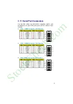
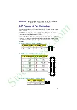
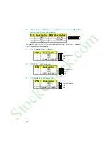
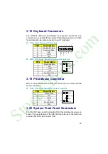
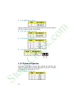
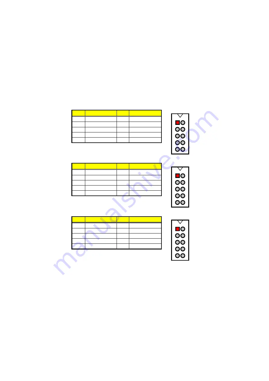
3.11  Serial Port Connectors 

The HS-7001 offers two NS16C550 compatible UARTs with 
Read/Receive 16-byte FIFO serial ports and four internal 10-pin 
headers.  


CN11: COM1 Connector (5x2 Header) 

PIN  Description  PIN  Description 

DCD0 

DSR0 

RXDD0 

RTS0 

TXDD0 

CTS0 

DTR0 

RI0 

GND 

10

N/C 


2

4

6

8

10

1

3

5

7

9

DSR0

RTS0

CTS0

N/C

RI0

DCD0

RXDD0

TXDD0

GND

DTR0


CN12: COM2 Connector (5x2 Header) 

PIN  Description  PIN  Description 

DCD1 

DSR1 

RXDD1 

RTS1 

TXDD1 

CTS1 

DTR1 

RI1 

GND 

10

N/C 


2

4

6

8

10

1

3

5

7

9

DSR1

RTS1

CTS1

N/C

RI1

DCD1

RXDD1

TXDD1

GND

DTR1


CN8: COM3 Connector (5x2 Header) 

PIN  Description  PIN  Description 

DCD2 

DSR2 

RXDD2 

RTS2 

TXDD2 

CTS2 

DTR2 

RI2 

GND 

10

N/C 


2

4

6

8

10

1

3

5

7

9

DSR2

RTS2

CTS2

N/C

RI2

DCD2

RXDD2

TXDD2

GND

DTR2


StockCheck.com

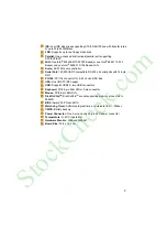
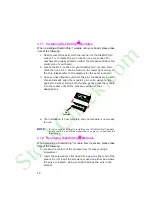
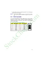
Summary of Contents for HS-7001

Page 1: ...478 Pentium 4 Industrial Single Board Computer Full size Giga LAN CRT ATA 33 66 100 Dual LAN Audio 4COM PC 104 IrDA USB2 0 DOC WDT H W Monitor PICMG Bus Industrial Single Board computer S t o c k C h...

Page 2: ...ion by BOSER Technology Co Ltd BOSER Technology Co Ltd reserves the right to change or improve the contents of this document without due notice BOSER Technology Co Ltd assumes no responsibility for an...

Page 3: ...m Memory 10 3 7 DiskOnChip Address Setting 10 3 8 VGA Controller 13 3 9 PCI E IDE Drive Connector 14 3 10 Floppy Disk Drive Connector 16 3 11 Serial Port Connectors 17 3 12 IrDA Connector 18 3 13 Para...

Page 4: ...CI Configurations 38 4 10 PC Health Status 39 4 11 Frequency Voltage Control 39 4 12 Load Fail Safe Defaults 40 4 13 Load Optimized Defaults 41 4 14 Set Supervisor User Password 42 4 15 Save Exit Setu...

Page 5: ...le from most electronic component stores when handling boards and components Fasten the ALLIGATOR clip of the strap to the end of the shielded wire lead from a grounded object Please wear and connect...

Page 6: ...S t o c k C h e c k c o m...

Page 7: ...GV 82801DB core logic chipset the board supports all PGA 478 Pentium 4 CPU series operating up to 2 8GHz The CRT display controller is Intel 82845GV with 1MB or 8MB memory supporting CRT display up to...

Page 8: ...tel 82551 10 100 Based and Intel 82562 10 100 Based LAN AC97 3D audio controller DiskOnChip TM socket supporting memory sizes of up to 288MB Supports USB2 0 two USB connectors Supports Hardware Monito...

Page 9: ...S 232 x 4 serial ports with 16 byte FIFO PC 104 PC 104 connector for 8 bit x 2clock ISA Bus IrDA One IrDA TX RX header USB Supports USB2 0 two USB connectors Keyboard PS 2 6 pin Mini DIN or 5 pin conn...

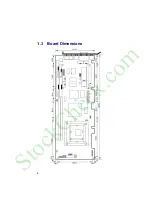
Page 10: ...4 1 3 Board Dimensions S t o c k C h e c k c o m...

Page 11: ...ce and carefully inspect the board for any damage that might have occurred during shipment Ground the board and exercise extreme care to prevent damage to the board from static electricity Integrated...

Page 12: ...t x 1 6 MIC Audio 8 pin cable x 1 7 Two COM flat cable with bracket x 2 It is recommended that you keep all the parts of the delivery package intact and store them in a safe dry place for any unforese...

Page 13: ...ess 1 Make sure that all jumper settings match their default settings and CMOS setup correctly Refer to the sections on this chapter for the default settings of each jumper Set JP2 1 2 2 Go through th...

Page 14: ...8 3 2 Board Layout S t o c k C h e c k c o m...

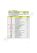
Page 15: ...n Keyboard Connector 22 CN7 Speaker Connector 23 CN11 CN12 CN8 CN9 COM1 COM4 Connector 5x2 header 16 CN10 MIC In Line Out Connector 25 CN13 5 pin ATX Power Connector 20 DM1 DM2 188 pin DDR Socket 10 F...

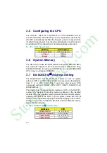
Page 16: ...ld support DDR 266 3 7 DiskOnChip Address Setting The DiskOnChip function allows the system to boot or operate without a FDD or a HDD DiskOnChip modules may be formatted as drive C or A With DiskOnChi...

Page 17: ...11 DC00H DDFFH 5 6 9 10 Short S t o c k C h e c k c o m...

Page 18: ...e s pins on an upright angle against the socket Using both thumbs gently press the module into the socket until all the pins are secured to their designations Pin 1 Location DiskOnChip 4 The installat...

Page 19: ...8 VGA Controller The onboard Intel 82845GV with 1MB or 8MB memory supporting CRT display up to 1280 x 1024 x 32 bit The HS 7001 provides one connection method of a VGA device VGA1 offers a single sta...

Page 20: ...ESET 2 GND 3 PDATA 7 4 PDATA 8 5 PDATA 6 6 PDATA 9 7 PDATA 5 8 PDATA 10 9 PDATA 4 10 PDATA 11 11 PDATA 3 12 PDATA 12 13 PDATA 2 14 PDATA 13 15 PDATA 1 16 PDATA 14 17 PDATA 0 18 PDATA 15 19 GND 20 N C...

Page 21: ...A 2 14 SDATA 13 15 SDATA 1 16 SDATA 14 17 SDATA 0 18 SDATA 15 19 GND 20 N C 21 SDREQ 22 GND 23 SIOW 24 GND 25 SIOR 26 GND 27 SIORDY 28 PR1SD1 29 SDDACK 30 GND 31 Interrupt 32 N C 33 SDA1 34 SATA66 35...

Page 22: ...DRVDEN0 3 GND 4 N C 5 GND 6 DRVDEN1 7 GND 8 INDEX 9 GND 10 MTR0 11 GND 12 DS1 13 GND 14 DS0 15 GND 16 MTR1 17 GND 18 DIR 19 GND 20 STEP 21 GND 22 WDATA 23 GND 24 WGATE 25 GND 26 TRAK00 27 GND 28 WRTPR...

Page 23: ...8 10 1 3 5 7 9 DSR0 RTS0 CTS0 N C RI0 DCD0 RXDD0 TXDD0 GND DTR0 CN12 COM2 Connector 5x2 Header PIN Description PIN Description 1 DCD1 2 DSR1 3 RXDD1 4 RTS1 5 TXDD1 6 CTS1 7 DTR1 8 RI1 9 GND 10 N C 2...

Page 24: ...GND DTR3 COM1 COM1 Connector DB9 PIN Description 1 DCD0 2 RXDD0 3 TXDD0 4 DTR0 5 GND 6 DSR0 7 RTS0 8 CTS0 9 RI0 1 6 5 9 DCD0 RXDD0 TXDD0 DTR0 GND DSR0 RTS0 CTS0 RI0 3 12 IrDA Connector IR1 is a 5 pin...

Page 25: ...GND 7 DATA 5 20 GND 8 DATA 6 21 GND 9 DATA 7 22 GND 10 Acknowledge 23 GND 11 Busy 24 GND 12 Paper Empty 25 GND 13 Printer Select 26 N C 1 14 26 13 Auto Form Feed ERROR Initialize Printer Select LN GN...

Page 26: ...Wake On LAN Connector PIN Description 1 PME 2 GND 3 VCC5SBY 1 3 3 15 USB Connector The HS 7001 provides one 8 pin USB2 0 connectors at locations USB1 for two USB connections to the HS 7001 USB1 USB2...

Page 27: ...nects to Backplane please make sure CN13 and Backplane s 5 pin ATX controller is connected together PW1 4 pin ATX Power Connector PIN Description PIN Description 1 GND 2 GND 3 12V 4 12V 1 2 3 4 GND 12...

Page 28: ...onboard HS 7001 are 3 pin chassis CPU System fan connector FN1 Chassis Fan Connector PIN Description 1 GND 2 12V 3 Chassis Fan Speed 1 GND 3 5V Chassis Fan Speed FN2 CPU Fan Connector PIN Description...

Page 29: ...ription 1 Keyboard Data 2 N C 3 GND 4 5V 5 Keyboard Clock 6 N C Keyboard Data N C GND 5V 1 2 3 4 5 6 Keyboard Clock N C 3 19 PS 2 Mouse Connector MS1 is a 6 pin Mini DIN connector for connections to a...

Page 30: ...end LED CN5 Keylock Connector PIN Description 1 5V 2 N C 3 GND 4 Keylock 5 GND CN2 Reset Button Connector PIN Description 1 GND 2 Reset 1 2 GND Reset 3 21 External Speaker Aside from the buzzer at loc...

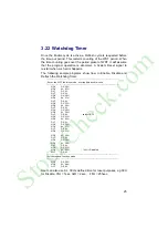
Page 31: ...the Watchdog Timer Enter the WDT function mode interruptible double write MOV DX 2EH MOV AL 87H OUT DX AL OUT DX AL MOV DX 2EH MOV AL 07H OUT DX AL MOV DX 2FH MOV AL 08H OUT DX AL MOV DX 2EH MOV AL F5...

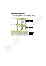
Page 32: ...t and the MIC In Line Out connectors CD1 CD ROM Analog Input Connector PIN Description 1 CD_R 2 CD_GND 3 CD_GND 4 CD_L 1 2 3 4 CD2 Line In Analog Input Connector PIN Description 1 LINE_IN_R 2 GND 3 GN...

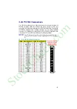
Page 33: ...e PC 104 connector allows direct plugging or stack through piling of PC 104 modules without requiring the PC 104 mounting kit PC2 PC 104 40 pin Connector PIN Description PIN Description 1 GND 21 GND 2...

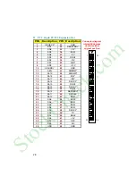
Page 34: ...SA19 44 SMEMR 13 SA18 45 IOW 14 SA17 46 IOR 15 SA16 47 DACK3 16 SA15 48 DRQ3 17 SA14 49 DACK1 18 SA13 50 DRQ1 19 SA12 51 REFRESH 20 SA11 52 SYSCLK 21 SA10 53 IRQ7 22 SA9 54 IRQ6 23 SA8 55 IRQ5 24 SA7...

Page 35: ...29 This page is intentionally left blank S t o c k C h e c k c o m...

Page 36: ...isks and then launch and turn control over to the operating system While the BIOS is in control the Setup program can be activated in one of two ways 1 By pressing Del immediately after switching the...

Page 37: ...r make changes key Increase the numeric value or make changes key Decrease the numeric value or make changes F1 key General help only for Status Page Setup Menu and Option Page Setup Menu Shift F2 key...

Page 38: ...984 2001 Award Software Standard CMOS Features Advanced BIOS Features Advanced Chipset Features Integrated Peripherals Power Management Setup PnP PCI Configurations PC Health Status Frequency Voltage...

Page 39: ...D correctly CMOS Setup Utility Copyright 1984 2001 Award Software Standard CMOS Features Date mm dd yy Wed Jul 11 2001 Item Help Time hh mm ss 10 32 57 Menu Level X X IDE Primary Master None X IDE Pri...

Page 40: ...vice Floppy Second Boot Device HDD 0 Change the day month Third Boot Device LS120 year and century Boot Other Device Enabled Swap Floppy Drive Disabled Boot Up Floppy Seek Enabled Boot Up Num Lock Sta...

Page 41: ...ver that the data has been lost while using your system CMOS Setup Utility Copyright 1984 2001 Award Software Advanced Chipset Features DRAM Timing Selectable By SPD Item Help CAS Latency Time 2 5 Men...

Page 42: ...UDMA Auto IDE Primary Slave UDMA Auto Change the day month On chip Secondary PCI IDE Enabled year and century IDE Secondary Master PIO Auto IDE Secondary Slave PIO Auto IDE Secondary Master UDMA Auto...

Page 43: ...o off In Suspend Yes year and century Suspend Type Stop Grant MODEM Use IRQ N A Suspend Mode Disabled HDD Power Down Disabled Soft off by PWR BTTN Instant Off CPU THRM throttling 50 00 Wake up by PCI...

Page 44: ...ettings CMOS Setup Utility Copyright 1984 2001 Award Software PnP PCI Configurations Reset Configuration Date Disabled Item Help Resources controlled By Auto ESCD Menu Level X IRQ Resources Press Ente...

Page 45: ...19V 5V 5 04 VBAT V 3 2V 5VSB V 5 00V Shutdown Temperature Disabled Select Item PU PD Value F10 Save ESC Quit F1 General Help F5 Previous Values F6 Fail Safe Defaults F7 Optimized Defaults 4 11 Freque...

Page 46: ...minimal performance system operations CMOS Setup Utility Copyright 1984 2001 Award Software X STANDARD CMOS Features X Frequency Voltage Control X Advanced BIOS Features Load Fail Safe Defaults X Adva...

Page 47: ...that are factory settings for optimal performance system operations CMOS Setup Utility Copyright 1984 2001 Award Software X Standard CMOS Features X Frequency Voltage Control X Advanced BIOS Features...

Page 48: ...ptions of the setup menus user password just can only enter but do not have the right to change the options of the setup menus When you select this function the following message will appear at the ce...

Page 49: ...s when trying to enter Setup 4 15 Save Exit Setup Pressing Enter on this item asks for confirmation Pressing Y stores the selections made in the menus in CMOS a special section of memory that stays on...

Page 50: ...ur computer CMOS Setup Utility Copyright 1984 2001 Award Software X Standard CMOS Features X Frequency Voltage Control X Advanced BIOS Features Load Fail Safe Defaults X Advanced Chipset Features Load...

Page 51: ...45 This Page is intentionally left blank S t o c k C h e c k c o m...
Page 52: ...drivers The following sections describe the installation procedures of each driver based on Win 95 98 Win 2000 and Win NT operating systems It is recommended that you install the drivers matching the...

Page 53: ...button to continue 3 Immediately after clicking the IDE button in Step 1 the program launches the InstallShield Wizard that will assist you in the installation process Click on the Next button to proc...

Page 54: ...tel OEM Software License Agreement dialog box then appears on the screen Choose Yes to proceed 5 When the Readme Information dialog box pops up just click on the Next button to proceed S t o c k C h e...

Page 55: ...ing your system it will prompt you to restart the computer Tick on the Yes I want to restart my computer now followed by a click on the Finish button to reboot Only after your computer boots will the...

Page 56: ...n Accelerator 1 Insert Utility CD Disk to your CD ROM drive The main menu will pop up as shown below Select on the HS 7001 button to launch the installation program 2 Click on the IDE Driver button to...

Page 57: ...appears make sure you close all other Windows applications then click on the Next button to proceed 4 The Intel OEM Software License Agreement dialog box then appears on the screen Choose Yes to proc...

Page 58: ...ve made your path installation choice 6 Once the setup program finishes copying files into your system it will prompt you to restart the computer Tick on the Yes I want to restart my computer now foll...

Page 59: ...1 Win 95 98 1 Insert Utility CD Disk to your CD ROM drive The main menu will pop up as shown below Select on the HS 7001 button to launch the installation program 2 Click on the VGA Driver button to...

Page 60: ...en the dialog box below appears make sure you close all other Windows applications then click on the Next button to proceed 5 The Intel OEM Software License Agreement dialog box then appears on the sc...

Page 61: ...u to restart the computer Tick on the Yes I want to restart my computer now followed by a click on the Finish button to reboot Only after your computer boots will the new settings take effect NOTE Ins...

Page 62: ...ady install Service Pack 6 0 1 Insert Utility CD Disk to your CD ROM drive The main menu will pop up as shown below Select on the HS 7001 button to launch the installation program 2 Click on the VGA D...

Page 63: ...7 3 Click on the Windows NT button to continue 4 When the dialog box below appears make sure you close all other Windows applications then click on the Next button to proceed S t o c k C h e c k c o m...
Page 64: ...ed 6 Once the setup program finishes copying files into your system it will prompt you to restart the computer Tick on the Yes I want to restart my computer now followed by a click on the Finish butto...

Page 65: ...Insert Utility CD Disk to your CD ROM drive The main menu will pop up as shown below Select on the HS 7001 button to launch the installation program 2 Click on the VGA Driver button to continue S t o...

Page 66: ...0 3 Click on the Windows 2K button to continue 4 When the dialog box below appears make sure you close all other Windows applications then click on the Next button to proceed S t o c k C h e c k c o m...
Page 67: ...ed 6 Once the setup program finishes copying files into your system it will prompt you to restart the computer Tick on the Yes I want to restart my computer now followed by a click on the Finish butto...

Page 68: ...1 Win 95 98 1 Insert Utility CD Disk to your CD ROM drive The main menu will pop up as shown below Select on the HS 7001 button to launch the installation program 2 Click on the LAN Driver button to...

Page 69: ...3 3 Click on the Windows 9x button to continue 4 When the dialog box below appears make sure you close all other Windows applications then click on the Next button to proceed S t o c k C h e c k c o m...

Page 70: ...Intel OEM Software License Agreement dialog box then appears on the screen Choose Accept to proceed 6 The Setup Type dialog box then appears on the screen Choose Typical to proceed S t o c k C h e c...

Page 71: ...ears make sure you close all other Windows applications then click on the Install button to proceed 8 When the dialog box below appears it means your driver is install completed Click Finish button to...

Page 72: ...ter boots will the new settings take effect 5 3 2 Win NT NOTE Please make sure you have already install Service Pack 6 0 1 The system automatically detects the absence of Windows NT Networking Click o...

Page 73: ...utton for the program to locate the Network Adapter 4 Once setup finishes the search it will list a number of adapters for you to choose from Press on the Have Disk button to assign the driver path lo...

Page 74: ...e 6 When Setup finds the information it needs about the new driver it will display the device it found on the following screen If using 82551 or 82562 please choose Intel R PRO 100 Family Adapter If u...

Page 75: ...reen and displays your new Network Adapter Click on Next to continue 8 The Network Setup Wizard then allows you to set the Network Protocols on your network Select the appropriate protocol and then cl...

Page 76: ...ollowing screen Click on the Next button once you are sure of your devices 10 Windows NT Setup will then need to copy files necessary to update the system information Specify the path then press Conti...

Page 77: ...ation and copies the files 13 When the screen below appears click on Next to continue 14 Setup then prompts you that it is ready to start the network You may complete the installation thereafter Click...

Page 78: ...the workgroup or domain setting of your computer Click on Next to continue 16 Click on the Yes button to restart your computer The LAN1 driver installation for WIN NT4 0 is now complete S t o c k C h...

Page 79: ...ck on Network Neighborhood icon from the desktop Select on Properties and then proceed to the Network from the main menu Click on Add to continue 18 Setup then returns to Network Setup Wizard screen a...

Page 80: ...nstallation for WIN NT4 0 is now complete 5 4 Audio Driver Installation 1 Insert Utility CD Disk to your CD ROM drive The main menu will pop up as shown below Select on the HS 7001 button to launch th...

Page 81: ...InstallShield Wizard completes the operation and update of your AC 97 driver it will ask you to remove disks from their drives and prompt you to restart your system Tick on the Yes I want to restart...

Page 82: ...5 1 Win 95 98 1 With the Utility CD Disk still in your CD ROM drive right click on My Computer icon from the Windows menu Select on System Properties and then proceed to the Device Manager from the m...

Page 83: ...he list of devices then double click on PCI Universal Serial Bus 3 The PCI Universal Serial Bus Properties screen then appears allowing you to re install the driver Select Driver from the main menu to...

Page 84: ...appears make sure you close all other Windows applications then click on the Next button to proceed 5 Tick on the Search for a better driver once the following screen appears Click on the Next to pro...

Page 85: ...our specified location will appear Press on the Next button to continue 7 When Setup finds the information it needs about the new driver it will display the device it found on the following screen Pre...

Page 86: ...ion process 5 4 2 Win 2000 1 With the Utility CD Disk still in your CD ROM drive right click on My Computer icon from the Windows menu Select on System Properties and then proceed to the Device Manage...

Page 87: ...n then appears allowing you to re install the driver Select Driver from the main menu to proceed 4 When the dialog box below appears make sure you close all other Windows applications then click on th...

Page 88: ...le driver once the following screen appears Click on the Next to proceed 6 Once the program returns to the Add New Hardware Wizard screen your specified location will appear Press on the Next button t...

Page 89: ...press on the Open button to accept and proceed 8 Once the InstallShield Wizard completes the operation and update of your USB2 0 driver Click on the Finish button to complete the installation process...

Page 90: ...sert Utility CD Disk to your CD ROM drive The main menu will pop up as shown below Select on the HS 7001 button to launch the installation program 2 Click on the USB2 0 Driver button to continue S t o...

Page 91: ...5 3 Click on the Windows XP button to continue 4 When the dialog box below appears make sure you close all other Windows applications then click on the Next button to proceed S t o c k C h e c k c o m...

Page 92: ...86 5 Once the InstallShield Wizard completes the operation and update of your USB2 0 driver Click on the Finish button to complete the installation process S t o c k C h e c k c o m...

Reviews: