11
z
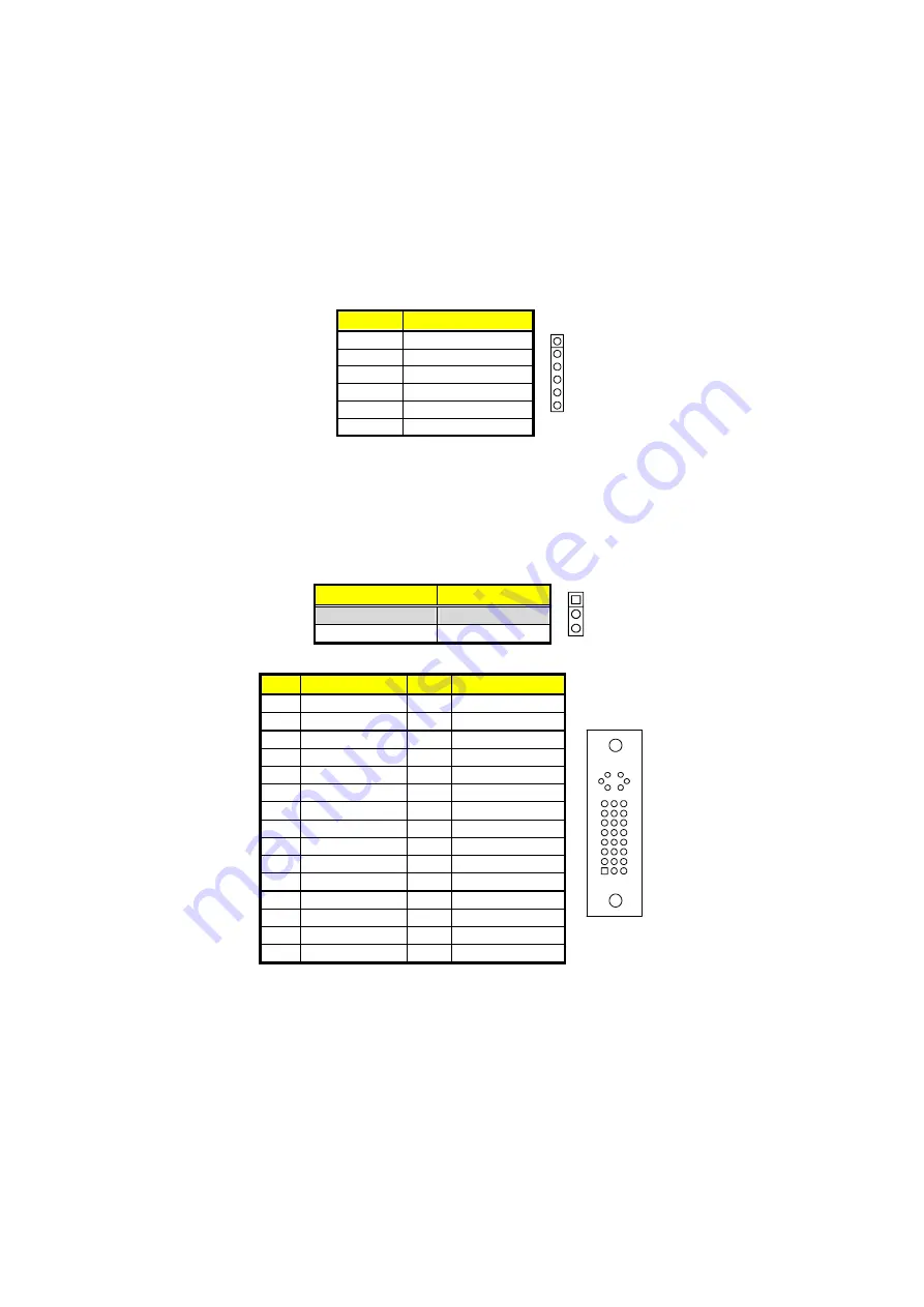
CN4: Inverter Power Connector
PIN
Description
1
6
1
+12V
2
+12V
3
VCC
4
BK_EN
5
LCD_EN
6
GND
NOTE:
If use JP3 only, it just supports 18-bit single channel LVDS panel;
If you want to use 36-bit dual channel LVDS panel, please use JP3
and JP2 combined.
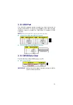
The HS-7280 has an onboard jumper that selects the working voltage
of the flat panel connected to the system. Jumper
JP1
offers two
voltage settings for the user.
z
JP1: Panel Voltage Select
Options
Settings
1
3
+3.3V (default)
Short 2-3
+5V
Short 1-2
z
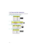
CN19: DVI-I Connector
PIN Description PIN Description
1
- DATA2
2
DATA2
3
GND
4
-DATA4
5
DATA4
6
DDCCLK
7
DDCDATA
8
VSYNC
9
-DATA1
10
DATA1
11
GND
12
-DATA3
13
DATA3
14
VCC5
15
GND
16
HPDET
17
-DATA0
18
DATA0
19
GND
20
-DATA5
21
DATA5
22
GND
23
CLK
24
-CLK
25
RED
26
GREEN
27
BLUE
28
HSYNC
29
GND
30
GND
Summary of Contents for HS-7280
Page 46: ...40 This page is the blank page...


