background image

17.

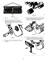
Install the 5 carriage bolts (3/8 x 1 inch) and 5
nuts (3/8 inch) to the side bracket. Torque the 5
nuts from this step and 2 nuts from the previous
step to 41 N·m (30 ft-lbs).

g371992

Figure 38

18.

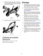
Install the lynch pin to the bristle carrier shaft.

g371999

Figure 39

Checking the Hydraulic
Fluid Level

Service Interval:

Before each use or daily

Refer to the

Operator’s Manual

.

Storage

1.

Park the machine on a level surface, engage
the parking brake, and move the motion-control
levers outward to the N

EUTRAL

-L

OCK

position.

2.

Shut off the engine and remove the key.

3.

Lower the kickstands so that the bristles are
not touching the ground; refer to

Using the

Kickstands (page 9)

.

Note:

The bristles will become deformed and

the broom will be out of alignment if the bristles
are touching the ground for an extended period
of time.

4.

Disconnect the hoses from the low-flow
assembly and connect the hoses together.

5.

Disconnect the hoses from the high-flow
assembly and connect the hoses together.

6.

Cover the couplers of the high-flow and low-flow
assemblies using caps or a bag.

7.

Oil the chain; refer to

Oiling the Chain (page 11)

.

8.

Thoroughly clean the broom and ensure that it is
free of all caustic chemicals and/or residue.

9.

Check and tighten all bolts, nuts, and screws.
Repair or replace any part that is damaged or
defective.

10.

Paint all scratched or bare metal surfaces. Paint
is available from your Authorized Service Dealer.

11.

Store the broom in a clean, dry garage or
storage area. Cover it to protect it and keep it
clean.

15


Summary of Contents for BRX25175

Page 1: ...Form No MSC23905 Rev B Owner s Manual 48in Broom Kit Snowrator MAG Part No BRX25175 Serial No 400000000 and Up Register at www bossplow com Original Instructions EN MSC23905 ...

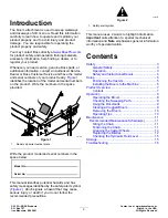
Page 2: ...al identifies potential hazards and has safety messages identified by the safety alert symbol Figure 2 which signals a hazard that may cause serious injury or death if you do not follow the recommended precautions g000502 Figure 2 1 Safety alert symbol This manual uses 2 words to highlight information Important calls attention to special mechanical information and Note emphasizes general informati...

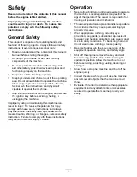
Page 3: ... with these safety instructions and always pay attention to the safety alert symbol which means Caution Warning or Danger personal safety instruction Failure to comply with these instructions may result in personal injury or death Operation Never allow children or untrained people to operate the machine Local regulations may restrict the age of the operator The owner is responsible for training al...

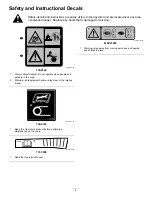
Page 4: ...16 8140 116 8140 1 Thrown object hazard Do not operate when people and pets are in the area 2 Warning Entanglement hazard stay clear of the rotating broom decal136 4146 136 4146 1 Read the Operator s Manual before performing maintenance on the chain decal137 3959 137 3959 1 Read the Operator s Manual decalmsc27245 MSC27245 1 Warning stay away from moving parts keep all guards and shields in place ...

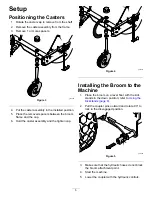
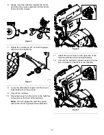
Page 5: ... and the cap 6 Hold the caster assembly and the tighten cap g372001 Figure 4 Installing the Broom to the Machine 1 Place the broom on a level floor with the kick stands in the down position refer to Using the Kickstands page 9 2 Pull the coupler pins outward and rotate 90 to lock in the disengaged position g371989 Figure 5 3 Make sure that the hydraulic hoses do not block the broom attachment poin...

Page 6: ... the broom kickstands rest on the ground 9 Shut off the machine 10 Route the hoses from the motor to the high flow connectors on the front of the machine Note Do not engage the high flow pump without the broom hydraulic hoses attached g372115 Figure 8 11 Attach the motor hoses to the right side of the machine with the hook and loop fastener 12 Connect the hydraulic cylinder hoses to the low flow c...

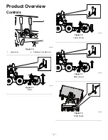
Page 7: ...Product Overview Controls g370669 Figure 10 1 Angle lever 2 Attachment coupler lever g374195 Figure 11 Float g374196 Figure 12 Lower broom g374197 Figure 13 Raise broom g372373 Figure 14 Right angle 7 ...

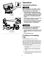
Page 8: ...om can throw stones and other foreign objects causing serious personal injury to you or bystanders Keep the working area clear and free of all objects that the broom could pick up and throw Keep bystanders away Checking the Sweeping Path Service Interval Before each use or daily A broom sweeps with the tips of its bristles When you apply too much downward pressure the broom no longer uses its tips...

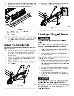
Page 9: ...le in the kickstand and release the handle g372005 Figure 19 Clearing a Clogged Broom WARNING The rotating broom could cause serious injury Shut off the machine and allow all rotating parts to stop before cleaning the broom 1 Stay in the operating position and release the left traction drive lever 2 While engaging the broom raise the broom above the ground If you cannot unclog the broom by lifting...

Page 10: ...n the machine g372126 Figure 20 8 Lower the coupler and move the machine rearward from the broom g372127 Figure 21 9 Arrange the hydraulic hoses on the broom and off the ground Operating Tips Become familiar with the area being swept Hidden obstructions such as curbs and pipes can damage the broom and or machine Do not let snow accumulate always sweep with the storm Always sweep at a safe speed Sw...

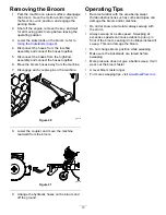
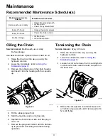
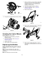
Page 11: ...e rubber plug on the chain housing and insert it into the housing with the cup side up g372006 Figure 22 4 Fill the rubber plug with oil 5 Start the machine and run it at low idle 6 Operate the broom at low idle until the plug is out of oil 7 Remove the plug and install it with the flat face up to prevent it from filling with debris during operation Tensioning the Chain Service Interval Every 40 h...

Page 12: ...eter Note Replace all bristles at the same time otherwise a mix of old and new bristles will reduce performance Note One side shown other side similar 1 Park the machine on a level surface disengage the broom move the motion control levers outward to the NEUTRAL LOCK position and engage the parking brake 2 Shut off the engine and remove the key 3 Lower the kickstands refer to Using the Kickstands ...

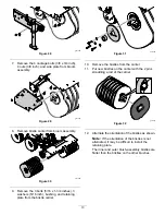
Page 13: ... and retaining plate from the bristle carrier g371995 Figure 31 10 Remove the bristles from the carrier 11 Put new bristles on the carrier with the 2 pins straddling a rod of the carrier g371997 Figure 32 12 Alternate the orientation of the bristles as shown Note If the orientation of the bristles is not alternated it may be difficult to install the retaining plate The inner and outer brush assemb...

Page 14: ...71995 Figure 34 14 Slide the carrier and new bristles on the broom assembly g371996 Figure 35 15 Install the 4 carriage bolts 3 8 x 3 4 inch 4 nuts 3 8 inch and side plate to broom assembly Torque the 4 nuts to 41 N m 30 ft lbs g371994 Figure 36 16 Install the 2 carriage bolts 3 8 x 1 inch 2 nuts 3 8 inch and side bracket to the broom assembly Do not torque the nuts at this time g371993 Figure 37 ...

Page 15: ...nds page 9 Note The bristles will become deformed and the broom will be out of alignment if the bristles are touching the ground for an extended period of time 4 Disconnect the hoses from the low flow assembly and connect the hoses together 5 Disconnect the hoses from the high flow assembly and connect the hoses together 6 Cover the couplers of the high flow and low flow assemblies using caps or a...

Page 16: ...om does not clean the surface 3 You are cleaning too much debris at one time 3 Slow down and clear smaller areas of debris 1 The broom is clogged 1 Unclog the broom 2 The broom drive lever is not engaged 2 Engage the broom drive lever The broom does not rotate 3 The drive chain is loose 3 Adjust the motor chain tension The broom wears out prematurely 1 You are using the incorrect broom height 1 Ad...

Reviews: