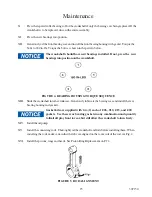
22
309150
XVI.
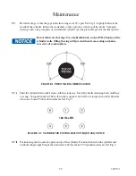
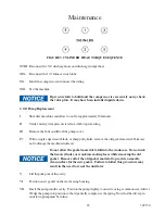
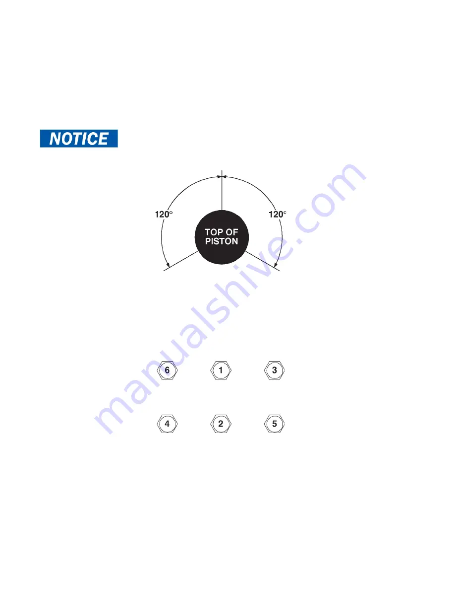
Slide the cylinder down until it mates with the crankcase. Start all cylinder mounting bolts, until they
are snug. Torque the bolts to 180 in-lbs in the sequence shown. Do not torque to the full 180 in-lbs
all at once, but in 25-50 in-lb increments. See Fig. 2.
Maintenance
FIGURE 1. PISTON RING ORIENTATION
XV.
Rotate the rings so that the gaps of the three rings are 120° apart. See Fig. 1. Lightly lubricate the
inside of the cylinder. Rotate the crankshaft so that a piston is at the top of the stroke. Compress
the rings with a ring compressor, and slide the cylinder over the piston. Repeat for the other piston.
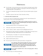
XVII. Position the gaskets and valve plate on top of the cylinder. Position the head on the cylinder and
turn bolts finger tight. Torque the studs/nuts to 240 in-lbs in 25-50 pound increments. See Fig. 3.
FIGURE 2. CYLINDER MOUNTING BOLT TORQUE SEQUENCE
180 IN-LBS
Do not lubricate the rings. Use a light lubricant, such as WD-40 only, on the
cylinder walls. Oiling the rings will prevent them from seating and cause
excessive oil consumption.
Summary of Contents for 36 BHP PISTON
Page 2: ...2 309150 ...
Page 28: ...28 309150 ...
Page 29: ...29 309150 WARRANTY SECTION ...
Page 34: ...34 309150 ...
Page 35: ...35 309150 PARTS AND ILLUSTRATION SECTION ...
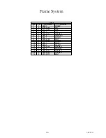
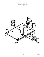
Page 37: ...37 309150 16 15 13 14 10 1 2 5 11 12 8 6 7 9 4 3 Frame System ...
Page 43: ...43 309150 13 6 5 3 7 1 4 4 2 10 11 12 9 8 16 14 15 16 Cooler System ...
Page 45: ...45 309150 3 1 10 7 2 4 6 5 13 12 11 9 8 Hydraulic Drive System ...
Page 47: ...47 309150 2 3 4 6 5 1 7 Discharge System ...
Page 49: ...49 309150 Canopy System 11 13 4 6 7 1 12 2 2 8 3 4 10 9 5 ...
Page 51: ...51 309150 2J 2B 2C 2D 2J 2H 2E 1 2I 2G 2A 2F Decal System ...
Page 52: ...52 309150 System Schematic ...


