6
309150
This manual must be read carefully before using your Boss Industries Air Compressor.
Store in a safe and convenient location for future reference.
For technical support:
Phone: (800) 635-6587 (USA)
Phone: (219) 324-7776 (Outside USA)
Fax: (877) 254-4249 (USA)
service@bossair.com (email)
http://www.bossair.com (website)
309150
10/29/2014 KWB
Service and
Maintenance
User Manual
Hydraulic Air Compressor
BOSS
36 BHP PISTON
Welcome
General Information
Thank you for choosing the Boss 36 BHP Hydraulic Air Compressor.
Before operating this compressor, read over this manual and become well
acquainted with your new machine. Doing this will increase your safety
and maximize the life of the machine.
While this manual is written to be as accurate as possible, Boss strives to
continually improve the efficiency and performance of its machines. As a
result, sometimes there may be slight differences between a given version
of the manual and the machine.
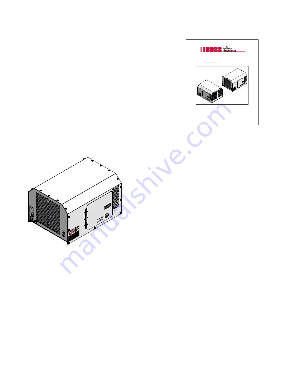
Boss 36 BHP Hydraulic Air Compressor
The Boss 36 BHP is a compact, strategically designed system. It integrates all major components on a single
frame, which is enclosed in a tough, weather-resistant canopy.
The 36 BHP Piston design provides output of up to 36
CFM (cubic feet of air per minute) at up to a maximum of
150 PSI (pounds per square inch). High output at
relatively low GPM (gallons per minute) translates into the
most efficient, quiet, and reliable system in its class,
designed to handle virtually any application.
The 36 BHP Piston also has enhanced safety features
offering applications designed to protect your most
valuable resource - your operating crew. To prevent
overheating, a high temperature switch will shut down the
machine in the event of high discharge temperatures.
Summary of Contents for 36 BHP PISTON
Page 2: ...2 309150 ...
Page 28: ...28 309150 ...
Page 29: ...29 309150 WARRANTY SECTION ...
Page 34: ...34 309150 ...
Page 35: ...35 309150 PARTS AND ILLUSTRATION SECTION ...
Page 37: ...37 309150 16 15 13 14 10 1 2 5 11 12 8 6 7 9 4 3 Frame System ...
Page 43: ...43 309150 13 6 5 3 7 1 4 4 2 10 11 12 9 8 16 14 15 16 Cooler System ...
Page 45: ...45 309150 3 1 10 7 2 4 6 5 13 12 11 9 8 Hydraulic Drive System ...
Page 47: ...47 309150 2 3 4 6 5 1 7 Discharge System ...
Page 49: ...49 309150 Canopy System 11 13 4 6 7 1 12 2 2 8 3 4 10 9 5 ...
Page 51: ...51 309150 2J 2B 2C 2D 2J 2H 2E 1 2I 2G 2A 2F Decal System ...
Page 52: ...52 309150 System Schematic ...


