background image

 28

COMPRESSOR OPERATION

OPERATING CONDITIONS

The following conditions should exist for maximum performance of the compressor.  The truck

should be as close to level as possible when operating.  The compressor will operate on a 15

degree sideward and lengthwise tilt without any adverse problems. Operation in ambient tempera-

tures above 100°F (38°C) may experience high temperature shutdown.

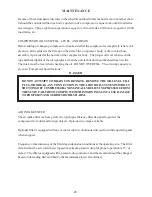
NOTE

NOTE

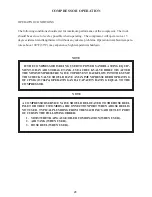
IF THE COMPRESSOR IS BEING USED TO POWER SANDBLASTING EQUIP-

MENT, OR AN AIR STORAGE TANK, USE A CHECK VALVE DIRECTLY AFTER
THE MINIMUM PRESSURE VALVE TO PREVENT BACKFLOW INTO THE SUMP.
THIS CHECK VALVE SHOULD HAVE A MAXIMUM PRESSURE DROP RATING
OF 2 PSIG (13.78kPa) OPERATING AND A CAPACITY RATING EQUAL TO THE
COMPRESSOR.

A  COMPRESSOR SERVICE VALVE SHOULD BE LOCATED TO THE HOSE REEL
INLET OR THE CUSTOMERS AIR CONNECTION PORT WHEN A HOSE REEL IS
NOT USED.  TYPICAL PLUMBING FROM THE MACHINE’S AIR OUTLET PORT
OCCURS IN THE FOLLOWING ORDER:

1.

MOISTURE TRAP/GAUGE/OILER COMBINATION (WHEN USED).

2.

AIR TANK (WHEN USED).

3.

HOSE REEL (WHEN USED).

Summary of Contents for Infinity

Page 1: ...BOSS MODEL INFINITY PTO AIR COMPRESSOR OPERATORS MAINTENANCE AND PARTS MANUAL P N 307200 06 05 2008 MCM ...

Page 2: ......

Page 3: ...ion Specifications 6 Safety 7 Compressor Terminology 11 Description of Components 12 Inspection Lubrication and Maintenance 16 Troubleshooting 24 Compressor Operation 27 Parts and Illustration Section 29 Recommended Spare Parts 36 Service Questionnaire 37 Instructional Procedures for Installation 38 Warranty Section Warranty Information 43 ...

Page 4: ......

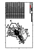
Page 5: ...OF REV 1 INFINITY 45 60 SCI8G 08 BOSS INDUSTRIES 1761 GENESIS DR LA PORTE IN 46350 N A PATH MATERIAL G Inventor Files 20k 20054 001 dwg 12 3 2007 12 3 2007 DCL DRAWN NDD CHECKED 1 4 D DESCRIPTION DWG NO R SCALE SIZE UNMACHINED SURFACES FRACTIONAL 1 16 DECIMAL 03 ANGULAR 1 DO NOT SCALE TOLERANCES UNLESS NOTED MACHINED SURFACES NOMINAL DIM 0 000 TO 1 000 010 1 001 TO 5 000 015 5 001 TO 10 000 020 10...

Page 6: ...re s or speed in excess of its rating as indicated in Compressor Specifications Periodically check all safety devices for proper operation Do not play with compressed air Pressurized air can cause serious injury to personnel Exercise cleanliness during maintenance and when making repairs by covering parts and exposed openings SAFETY ALLUNITSARE SHIPPED WITHADETAILED OPERATORSAND PARTS MANUAL THIS ...

Page 7: ...ied and forewarned that any failure to observe these safety precautions may result in damage or injury BOSS INDUSTRIES INC expressly disclaims responsibility or liability for any injury or damage caused by failure to observe these specified precautions or by failure to exercise that ordinary caution and due care required when operating or handling the Compressor even though not expressly specified...

Page 8: ...ng decals is supplied with each unit These decals must be affixed to the comressor package in the locations noted in this manual If for any reason a safety decal is removed it is the owners responsibility to make sure it is replaced ...

Page 9: ...10 SAFETY ...

Page 10: ...ATF GPM Refers to the amount of gallons per minute of hydraulic fluid flowing through the pump OIL SUMP The first stage of oil separation from compressed air Also serves as reservoir area for compressor lubricant and sometimes referred to as the receiver tank PSI Refers to the operating pressure the system is set up at expressed as pounds per square inch SAFETYVALVE Avalve located on the oil sump ...

Page 11: ...wing pulse free air to the receiver During the compression cycle oil is injected into the compressor and serves these purposes 1 Lubricates the rotating parts and bearings 2 Serves as a cooling agent for the compressed air 3 Seals the running clearances LUBRICATION SYSTEM Oil from the compressor at discharge pressure is directed into its integral housing through the thermal valve and filter and th...

Page 12: ...um discharge pressure of 75 PSIG in operation which is required to assure adequate compressor lubrication pressure OIL FILTER The compressor oil filter is a removable and cleanable screen built into the side of the compressor housing Screen replacement may be necessary after several cleanings COMPRESSOR OILAND HYDRAULIC OIL COOLING SYSTEMS The compressor cooling system consists of a combination hy...

Page 13: ...eswitchgaugeensuressafety shutdown in case of excessive operating temperatures preventing compressor damage by stopping hydraulicflowtothecompressormotor ELECTRICALAND SAFETYSYSTEM The BOSS INDUSTRIES compressor s standard electrical system consists of Gaugepanelwithatemperatureswitchgauge hourmeteranddischargepressureswitchgauge Compressor and hydraulic oil cooler fan assembly and relay Compresso...

Page 14: ...the tool manufacturer and the specifications of the equipment that work is being performed on FURNAS SWITCH DESCRIPTION The Furnas switch is a N C electrical switch set to open at 150 PSI and set to close at 115 PSI The Furnas switch controls the N O regulator solenoid If service air pressure is under 150 PSI the Furnas switch will not trip keeping the N O inlet valve open and the compressor makin...

Page 15: ...ly visual inspections should become a routine The LUBRICATIONAND MAINTENANCE CHART lists serviceable items on this compressor package The items are listed according to their frequency of maintenance followed by those items which need only As Required maintenance The maintenance time intervals are expressed in hours The hourmeter shows the total number of hours your compressor has run Use the hourm...

Page 16: ... o f k c e h C 3 s e h c t i w s t i u c r i c y t e f a s k c e h C 4 S R U O H 5 2 Y R E V E Y L H T N O M R O l i o r o s s e r p m o c m o r f r e t a w n i a r D 1 0 0 5 Y R E V E 6 R O S R U O H S H T N O M n e e r c s e c a l p e r d n a l i o r o s s e r p m o c e g n a h C 1 e g a k a e l r o f l a e s t f a h s r o s s e r p m o c k c e h C 2 s p m a l c d n a s g n i t t i f g n i p i p...

Page 17: ...s own knowledge of the suitability of the recommended lubricant in helical screw type air compressors operating in the particular environmentinvolved CAUTION IT IS IMPORTANT THAT THE COMPRESSOR OIL BE OF A RECOMMENDED TYPE AND THAT THIS OIL AS WELL AS THE AIR FILTER OIL FILTER AND COALESCER ELEMENTS BE INSPECTEDAND REPLACEDAS STATED INTHIS MANUAL THE COMBINATION OFACOALESCER ELEMENT LOADED WITH DI...

Page 18: ...ilizer NOTE NOTE DUETO ENVIRONMENTALFACTORS THE USEFULLIFE OFALL EXTENDED LIFE LUBRICANTS MAYBE SHORTER THAN QUOTED BYTHE LUBRICANT SUPPLIER BOSS INDUSTRIES INC ENCOURAGES THE USER TO CLOSELY MONITOR THE LUBRICANT CONDITION AND TO PARTICIPATE IN AN OIL ANALYSIS PROGRAM WITH THE SUPPLIER NO LUBRICANT HOWEVER GOOD AND OR EXPENSIVE CAN REPLACE PROPER MAINTENANCEANDATTENTION SELECTAND USE ITWISELY ...

Page 19: ... DO NOT OVERFILL The oil sump capacity is given in Compressor Specifications DANGER AIR INTAKE FILTER The air intake filter is a heavy duty dry type high efficiency filter designed to protect the compressor from dust and foreign objects Optional two stage available Optional filter is equipped with an evacuator cup for continuous dust ejection while operating and when stopped Frequency of maintenan...

Page 20: ... by hand until element contacts seal viewing element from bottom 5 Rotate element approximately one more turn clockwise with band wrench near the top of element 6 Run system and check for leaks WARNING COALESCER OIL RETURN This originates at the bottom of the air oil coalescer and flows through a special recovery pipe and venturi nozzle If the coalescer starts to fill with oil there is a good chan...

Page 21: ...ATION The interior of the oil cooler should be cleaned when the pressure drop across it at full flow exceeds 25 PSI The following procedure has been recommended by the vendor who supplies the cooler 1 Remove cooler 2 Circulate a suitable solvent to dissolve and remove varnish and sludge 3 Flush generously with compressor lubricant compressor oil cooler section only use hydraulic oil to flush the h...

Page 22: ...emoving all burrs from shaft where the wear sleeve gets installed 6 Press new wear sleeve on to shaft Oil heating new wear sleeve to 212 F approximately aids in the installation of this ring 7 Press new seal into housing with seal assembly tool until contact with snapring 8 Temporarily install new seal installation cone over shaft to protect seal during reinstallation 9 Reinstall cover 10 Reinstal...

Page 23: ...e has been interrupted by an unexplained shutdown check the following 1 Check the fuel level and truck dash gauges and indications for possible engine problems 2 Check the compressor discharge temperature switchgauge If the latching relay circuit is tripped the 12VDC solenoid will lose power and divert hydraulic oil back to the reservoir The compressor blowdown pressure switch and the temperature ...

Page 24: ...chgauge B Coalescer plugged up C Faulty safety valve D N O regulated air solenoid is not opening E Furnas switch is not opening at 150 psi 3 Sump relief valve activates A Inlet valve leaking or open B Faulty relief valve C Faulty Furnas switch or N O regulated air solenoid or pressure switchgauge SUMP PRESSURE DOES NOT BLOW DOWN If after the compressor is shutdown pressure does not automatically b...

Page 25: ...or a number or reasons 1 Extreme operating temperature 2 negligence in draining condensate from oil sump 3 using the improper type of oil 4 dirty oil 5 oil return nozzle plugged The complete air inlet system should be checked for leaks HIGH COMPRESSOR DISCHARGE TEMPERATURE 1 Check compressor oil level Add oil if required see Section for oil specifications 2 Check thermal valve operation 3 Clean ou...

Page 26: ... c i d n I f o p o t d n a t n i o p d i m n e e w t e b e b d l u o h s l e v e l e h t n e h w l e v e l s i h t k c e h C s s a l g t h g i s e h t s i e l c i h e v e h t d n a d e g a g n e s i d s i r o s s e r p m o c d n u o r g l e v e l n o d e k r a p F E I L E R E R U S S E R P E V L A V f i e r e h p s o m t a e h t o t e r u s s e r p p m u s s t n e V 5 7 1 s d e e c x e p m u s e h...

Page 27: ...OMPRESSOR IS BEING USED TO POWER SANDBLASTING EQUIP MENT OR AN AIR STORAGE TANK USE A CHECK VALVE DIRECTLYAFTER THE MINIMUM PRESSURE VALVE TO PREVENT BACKFLOWINTOTHE SUMP THIS CHECK VALVE SHOULD HAVE A MAXIMUM PRESSURE DROP RATING OF 2 PSIG 13 78kPa OPERATING AND A CAPACITY RATING EQUAL TO THE COMPRESSOR A COMPRESSOR SERVICEVALVE SHOULD BE LOCATED TO THE HOSE REEL INLET ORTHE CUSTOMERSAIR CONNECTI...

Page 28: ...29 PARTS AND ILLUSTRATION SECTION ...

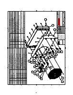
Page 29: ...ONAL 1 16 DECIMAL 03 ANGULAR 1 DO NOT SCALE TOLERANCES UNLESS NOTED MACHINED SURFACES NOMINAL DIM 0 000 TO 1 000 010 1 001 TO 5 000 015 5 001 TO 10 000 020 10 001 OVER 025 THIS DRAWING AND ALL ITS CONTENTS ARE PROPERTY OF BOSS INDUSTRIES INC AND MUST NOT BE COPIED OR MADE PUBLIC IT IS LOANED AND IS SUBJECT TO RETURN UPON DEMAND THE INFORMATION CONTAINED IN THIS DRAWING IS CONFIDENTIAL AND MUST NOT...

Page 30: ...BSPP FS 973108 050 1 30 WASHER FLAT 10MM 938910 200 5 31 NUT COALESCER REV 4 300233 1 32 WASHER LOC GR8 3 8 937806 094 2 33 WASHER FLAT GR8 3 8 938206 071 2 34 BOLT HEX GR10 9 10MM X 25MM 929210 250 8 35 BRACKET RELAY MTG REV 7 302608 1 36 DECAL TEMP COMPR 250 F 301594 1 37 DECAL TEMP HYD 140 F30 301593 1 38 ADAPTER 1 2 MNPT X 1 2 FJIC 307201 1 39 DECAL DIRECTION OF ROTATION 300048 1 40 WASHER BRA...

Page 31: ...23 DECAL SERIAL TAG BOSS REV 1 305761 1 24 GROMMET 1 7 8 OD X 1 1 4 ID X 1 16 THK 307433 1 25 CLIP 1 2 HYD HOSE HOLDER 302613 2 26 TAPE 1 16 X 1 2 CLOSED CELLO 300444 8 FT NS SHEET 200354 1 1 OF REV 1 CANOPY SYS INFINITY 45 60 150 SCI8G 08 BOSS INDUSTRIES 1761 GENESIS DR LA PORTE IN 46350 N A PATH MATERIAL G Inventor Files 200k 200354 dwg 12 3 2007 12 3 2007 DCL DRAWN NDD CHECKED 1 4 D DESCRIPTION...

Page 32: ... 08 2 1 300074 GAUGE HOURMETER 3 1 302449 LIGHT INDICATING GREEN 4 2 302450 LIGHT INDICATING RED 5 1 302592 SWITCH N O MOMENTARY SPST 6 1 302486 BREAKER PANEL MTG RESET 7 3 929705 100 BOLT WHIZLOCK GR5 5 16 18 X 1 8 3 961505 140 NUT TINNERMAN 5 16 18 9 1 307191 DECAL INFINITY 08 GAUGE PANEL 10 1 300076 004 SWITCHGAUGE TMP 4 ft 250 11 1 300075 SWITCHGAUGE PRESSURE 12 1 302591 SWITCH SHUTDOWN 117LF ...

Page 33: ... WHIZLOCK GR5 5 16 18 X 1 4 1 302622 FAN ASSY WITH MOTOR AND GRILL 14 09 PUSHER CURVED BLADE 5 2 960108 075 CONNECTOR 1 2 MJIC X 3 4 MNPT 6 1 960208 050 ELBOW 1 2 JIC X 1 2 MNPT 7 1 984112 050 ELBOW HYD 3 4 MNPT X 1 2 MNPT 8 1 907215 020 COUPLING PIPE 1 2 GAL 150 PSI 9 14 961505 140 NUT TINNERMAN 5 16 18 10 1 961612 050 NIPPLE HYD HEX RED 3 4 X 1 2 11 1 960112 075 CONNECTOR 3 4 MJIC X 3 4 MNPT 12 ...

Page 34: ...35 ...

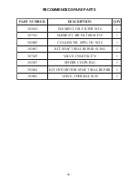
Page 35: ... C S R E T L I F R I A T N E M E L E 1 0 0 6 2 0 3 8 I C S N O N I P S R E C S E L A O C 1 3 0 6 2 0 3 G 8 I C S R I A P E R L A E S T F A H S T I K 1 9 4 1 7 0 3 8 7 I C S T E L N I E V L A V 1 3 0 1 2 0 3 G N I L P U O C R E D I P S 1 4 0 6 2 0 3 R I A P E R L A E S T F A H S R O T O M D Y H T I K 1 2 0 6 2 0 3 8 I C S L A M R E H T E V L A V 1 ...

Page 36: ... _ _ _ _ _ _ _ _ _ _ _ _ _ _ _ _ _ _ _ _ _ _ _ _ _ _ _ _ _ _ _ _ _ _ _ _ _ _ _ _ _ _ _ _ _ _ _ _ _ _ _ _ _ _ _ _ _ _ _ _ _ _ _ _ _ _ _ _ _ _ _ _ _ _ _ _ _ _ _ _ _ _ _ _ _ _ _ _ _ _ _ _ _ _ _ _ _ _ _ _ _ _ _ _ _ _ _ _ _ _ _ _ _ _ _ _ _ _ _ _ _ _ _ _ _ _ _ _ _ _ _ _ _ _ _ _ _ _ _ _ _ _ _ _ _ _ _ _ _ _ _ _ _ _ _ _ _ _ _ _ _ _ _ _ _ _ _ _ _ _ _ _ _ _ _ _ _ _ _ _ _ _ _ _ _ _ _ _ _ _ _ _ _ _ _ _ _ _ _ _...

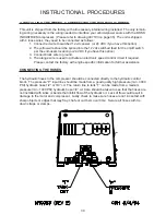
Page 37: ... except with written factory approval 1 MOUNTING COMPRESSOR When mounting the compressor care should be taken to ensure that its location does not im pede the operation of other components on the vehicle For example if your vehicle is equipped with a crane you must make sure the compressor will not interfere with the swing of the crane In addition the compressor should be installed in an area that...

Page 38: ... to ground 4 The orange wire is used to activate an electronic speed control circuit if required Please contact the factory with engine specific information for further assistance CONNECTING THE HOSES The hydraulic hoses to the compressor should be connected directly to the hydraulic control block The pressure P input line should be made from a good quality high pressure min 3000 PSI hydraulic hos...

Page 39: ...y tied and secured to the vehicle This is a very critical area of inspection The vehicle should not be moved until this inspection has been completed V Record all serial numbers for this installation A Vehicle V I N B Hydraulic Pump Data C Air End Serial Number D BOSS INDUSTRIES Serial Number E Receiver Tank Serial Number F Note any special applications relating to specific installations VI Check ...

Page 40: ...N EXTENSIVE COMPRESSOR UNIT DAMAGE The safety shutdown switch should be wired in series with the solenoid that opens the flow of the hydraulic oil to the compressor drive motor In cases of high temperature and or pressure the closing of the valve will stop the compressor operation Safety circuit testing for INFINITY Safety circuit testing can be done in the following manner Start the truck Engage ...

Page 41: ...42 WARRANTY SECTION ...

Page 42: ...ressor unit is disassembled the warranty is void BOSS ssoleresponsibilityandBuyer sexclusiveremedyhereunderislimitedtosuchrepair replacement or repayment of the purchase price Parts not of BOSS manufacture are warranted only to the extent that they are warranted by the original manufacture BOSS shall have no responsibility for any cost or expense incurred by Buyer from inability of BOSS to repair ...

Page 43: ...fmaterialdefectofdefective workmanshipwillcausewarrantyclaimtoberejected Defective material must be returned within 30 days of receipt of shipping instructions Failure to do so withinspecifiedtimewillresultinforfeitureofclaim Thedistributorisresponsiblefortheinitialinvestigationandwriteupofthewarrantyclaim Distributor shall be allowed no more than 30 days from date of repair to file a warranty cla...

Page 44: ... 1 ReturnGoodsAuthorization 2 Distributor or end users return address 3 Correct factory address 4 Number of packages pertaining to each claim NOTE Our warranty requires that all defective parts be returned to BOSS INDUSTRIES freight prepaid ItemssentwithoutRGAnumberwillnotbeaccepted UnauthorizedReturnsWillImmediately Be RefusedAt Dock RETURN OR WARRANTYCLAIMS FILING PROCEDURES 1 Initiate through a...

Page 45: ...eliveryofthe kit or factory installed unit was assumed by the carrier at the time of shipment Therefore claims for loss or damage to the contents of the kit or factory installed unit should be made upon the carrier 2 Concealed loss or damage Concealed loss or damage means loss or damage which does not become apparent until the kit is unpacked or the factory installed unit is run by the end user Th...

Page 46: ...AM Replacement air ends are available from the factory For current prices and availability contact BOSS INDUSTRIES Inc or an authorized BOSS INDUSTRIES distributor Prices are F O B shippingpoint Pricesdonotincludelaborforremovalorinstallation ...

Reviews: