39
INSTRUCTIONAL PROCEDURES
2. INSTALLING THE WIRING & CONNECTING THE HYDRAULIC HOSES
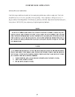
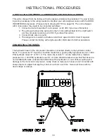
This unit is shipped from the factory with all necessary internal wiring installed. The only remain-
ing wiring necessary is the wiring needed to interface your vehicle/power source with the BOSS
INDUSTRIES compressor. (Please refer to drawing 307193 on page 35) The unit is shipped
with 4 loose wires, they need to be connected as follows:
1. Connect red wire to switched 12 vdc power. (or 24 VDC if you have this option)
2. The yellow wire should be spliced into the 12 vdc switched feed for the on/off switch
per the end-users location.(or 24 VDC if you have this option)
3. Connect black wire to ground.
4. The orange wire is used to activate an electronic speed control circuit if required.
Please contact the factory with engine specific information for further assistance.
CONNECTING THE HOSES
The hydraulic hoses to the compressor should be connected directly to the hydraulic control
block. The pressure “P” input line should be made from a good quality high pressure (min. 3000
PSI) hydraulic hose 1/2” or 3/4” i.d. The return line to tank “T” can be made from a medium
pressure (min. 1000 PSI) hydraulic hose 3/4” i.d. Care should be taken to see that the hoses are
not installed with kinks or bends that inhibit flow of the hydraulic oil. Lack of flow could result in
damage to the motor and compressor. Lastly check to make sure hoses are not in contact with
sharp objects or edges that may fray, chafe or cut them over time. Secure all hoses with tie
down straps or clamps.
Summary of Contents for Infinity
Page 2: ......
Page 4: ......
Page 9: ...10 SAFETY ...
Page 28: ...29 PARTS AND ILLUSTRATION SECTION ...
Page 34: ...35 ...
Page 41: ...42 WARRANTY SECTION ...


