background image

Electrical System Wiring Procedure 

13 


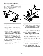
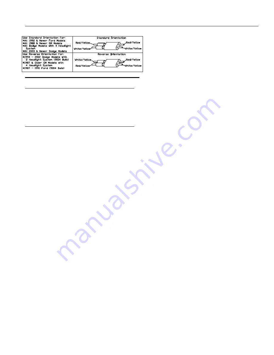
Figure 21.

 Vehicle Option Connector 

G10202


NOTICE 

All plow wiring should be secured within the 
engine compartment in a position that provides 
sufficient room so that hot or moving parts will 
not be contacted. Vehicle damage could occur if 
wires are not properly secured.


32.  Locate vehicle option connector.  Align the 

connector so that the arrow on the Vehicle Option 
Connector is positioned to match the vehicle it is 
installed on. This is illustrated in Figure 21. 


Note:

  If your vehicle is not listed in the above figure 

use the Standard Orientation. If the Vehicle Option 
Connector is not properly connected the lights on the 
plow will not function correctly. 
 
33.  Secure all plow harness wiring. 
 
34.  Attach the snowplow to the vehicle. Use the 

“Snowplow Mounting Procedure” that is located in 
this manual to properly attach the snowplow to the 
vehicle. 

 
35.  Test for the proper operation of the Headlight 

Wiring Harness. Follow the procedures below. 


Note:

  To test plow lights, the 

IGNITION

 must be in 

the 

ON

 position. 


LOW BEAM (Truck Lights) 


Vehicle Headlight Switch – ON 


Low Beam Lights on Truck Indicator 


Plow Headlight Toggle Switch –TRUCK 


RESULTS

 - ONLY vehicle low beam headlights should be illuminated. 


HIGH BEAM (Truck Lights) 


Vehicle Headlight Switch – ON 


High Beam Indicator Light – ON   


Plow Headlight Toggle Switch –TRUCK 


RESULTS

 - Only vehicle high beam headlights should be illuminated. 


LOW BEAM (Plow Lights) 


Ignition - ON 


Vehicle Headlight Switch – ON 


Low Beam Lights on Truck Indicator   


Plow Headlight Toggle Switch - PLOW  


RESULTS

 - ONLY plow low beam headlights should be illuminated.  


HIGH BEAM (Plow Lights) 


Ignition - ON 


Vehicle Headlight Switch – ON 


High Beam Indicator Light – ON 


Plow Headlight Toggle Switch – PLOW 


RESULTS

 - Only plow high beam headlights should be illuminated. 


TURN SIGNALS (Plow and Truck) 


Left Turn Signal Indicator – ON 


RESULTS

 - Both Left Plow and Left Truck turn signal bulbs should 

be flashing. 


Right Turn Signal Indicator – ON 


RESULTS

 - Both Right Plow and Right Truck turn signal bulbs 

should be flashing. 


Park Lights (Plow and Truck) 


Park Lights on Vehicle – ON


RESULTS

 - All four, Left Plow, Right Plow, Left Truck, and Right 

Truck Park Lights should be on.


Note:

  If any of the lights are not working properly, re-

check the wiring against the “Electrical Wiring 
Diagram” located in this manual and make any 
necessary corrections.

Summary of Contents for SMARTHITCH2 RT3 POWER-V

Page 1: ...IGHT AIMING PROCEDURE 20 HYDRAULIC POWER UNIT FILL PROCEDURE 21 V BLADE CONTROLLERS 22 TROUBLESHOOTING GUIDE 26 RECOMMENDED PUSHBEAM HEIGHT 32 RECOMMENDED BOLT TORQUE 32 BOSS PRODUCTS Northern Star Industries Inc reserves the right under its continuous product improvement policy to change construction or design details and furnish equipment when so altered without reference to illustrations or spe...

Page 2: ... bag WARNING Read this manual carefully before operating this snowplow WARNING When transporting position plow so as not to block vision or plow headlights WARNING DO NOT change blade position when traveling WARNING DO NOT exceed 40 mph when transporting plow WARNING DO NOT exceed 14 mph when plowing WARNING Always lower blade when vehicle is not in use WARNING Make sure plow is properly attached ...

Page 3: ...Snowplow Mounting Procedure 3 Figure 1 Mounting and Removal Instructions MSC04606 ...

Page 4: ... the center bushings on Right Blade Half 4 Position CHA09716 Center Section 2 on top of both blades so that all bushings align 4 Insert MSC01507 Center Hinge Pin 15 through Left Blade Half 5 Right Blade Half 4 and Center Section 2 5 Secure Center Hinge Pin 15 to the top of Center Section 2 using one HDW01771 3 8 16 X 1 Hex Head Cap Screw 93 and one HDW01718 3 8 Split Lock Washer 108 Note Plow shoe...

Page 5: ... Head Cap Screws 90 and HDW01709 5 8 11 Self Locking Nuts 111 DO NOT over tighten the nuts Note You should be able to slightly slide the cylinder up and down on the bolt after it has been tightened Figure 4 Angle Cylinder Installation G10121 13 Pull both wings back into the V position 14 Hook one end of Return Spring 19 to the top hole on Center Section 2 Hook the opposite end of Return spring 19 ...

Page 6: ...Springs 18 on Push Frame 3 until there is a 1 32 space between each spring coil Figure 6 Assembly of Lift Cylinder Hydraulics G10138 20 Remove the plug from the top end of Lift Cylinder 42 21 Attach one end of Hydraulic Hose 50 to Lift Cylinder 42 Be sure to apply thread sealant compound to the pipe threads on Hydraulic Hose 50 Tighten connection securely 22 Attach the top end of Lift Cylinder 42 ...

Page 7: ...lic system 26 Attach the loose end of HYD07042 Hydraulic Angle Hose 52 to the corresponding fitting on the hydraulic manifold Tighten all hydraulic connections securely Figure 8 Light Bar Assembly Standard G10132 27 Attach Light Bar 13 to the top of Coupler Assembly 1 using two Hex Head Cap Screws 91 and Hex Head Self Locking Nuts 109 Note The light bar should be positioned as close to the Coupler...

Page 8: ...r s Side Headlight 76B and Passenger s Side Turn Signal 76C Figure 11 Secure Wiring Harness G10126 32 Secure Wiring Harness 61 to Light Bar 13 as shown above 33 Insert the unconnected ends of the Plow Wiring Harness into the back of the coupler through the rubber grommet 34 Connect the Plow Side Wiring Harness to the Hydraulic Valve Manifold as shown in Figure 26 HYD07044 with SmartHitch2 TM Wirin...

Page 9: ... the back of the driver s side vehicle headlight 3 Connect the Black Rubber Connector B from Wiring Harness 60 into the OEM Wiring Harness C OEM Wiring Harness C is the vehicle connector that was unplugged from the back of the headlight in Step 1 Note If your connectors do not match the connectors on the wiring harness or you have a four headlight system a Headlight Adapter Kit will be needed If y...

Page 10: ...area Figure 16 Internal Cab Wires G10144 11 Pull the two BLACK wires H BLACK RED wire I and the 9 Pin Molex connector G from the engine compartment into the cab through the 1 1 4 diameter hole in the firewall 12 Install MSC03761 Split Rubber Grommet Not Shown into the hole that was cut in the firewall 13 Connect the Two Tab Connectors H to MSC04747 Headlight Toggle Switch 77A as illustrated in the...

Page 11: ...Wiring Harness 60 to the small terminal on Pump Solenoid 64 Note Location of the wires on the small terminals does not matter 22 Attach Power Unit Solenoid 64 securely inside the engine compartment The Power Unit Solenoid should be mounted in the upright position as illustrated above Note The solenoid must be installed so that the solenoid posts do not contact the body hood or any other conductive...

Page 12: ...racket 30 Mount the BLACK and RED 2 Pin Power Ground Connector to the lower area of the bumper using MSC03491 Power Ground Mounting Bracket Note Installation location will vary depending on truck Figure 20 Relay Mounting G10152 31 Attach the Relay Pack securely to the inside of the engine compartment using four HDW01766 Sheet Metal Screws The relays should be positioned upright as illustrated abov...

Page 13: ...cle Headlight Switch ON Low Beam Lights on Truck Indicator Plow Headlight Toggle Switch TRUCK RESULTS ONLY vehicle low beam headlights should be illuminated HIGH BEAM Truck Lights Vehicle Headlight Switch ON High Beam Indicator Light ON Plow Headlight Toggle Switch TRUCK RESULTS Only vehicle high beam headlights should be illuminated LOW BEAM Plow Lights Ignition ON Vehicle Headlight Switch ON Low...

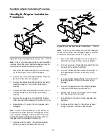
Page 14: ...is case only three adapters will be needed Follow the Headlight Adapter Installation Instructions that are packaged with the Headlight Adapter Kit 7 Continue with the Step 7 of Electrical System Wiring Procedure located in this manual Figure 23 Dual Headlight Adapter Connections G10151 Note This is a general diagram for most 4 headlight vehicles All vehicles and headlight adapters may not be ident...

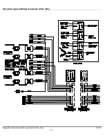
Page 15: ...Electrical System Wiring Schematic Plow Side 15 Figure 24 Electrical System Wiring Schematic Plow Side G10271 ...

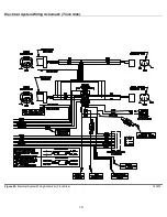
Page 16: ...Electrical System Wiring Schematic Truck Side 16 Figure 25 Electrical System Wiring Schematic Truck Side G10272 ...

Page 17: ...Electrical System Wiring Diagram 17 Figure 26 Electrical System Wiring Diagram G10134 ...

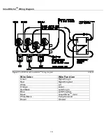
Page 18: ... HYD07044 with SmartHitch2 TM Wiring Diagram G10445 Wire Color Wire Function Green Right Wing In Red Right Wing Out White Lift Orange Lower Red Black Left Wing In Blue Left Wing Out Black SmartHitch2TM 12V White Black Pump Solenoid Brown Ground ...

Page 19: ...Blade w SmartHitch2 TM HYD07044 1 31A Valve Lift Angle HYD01637 6 31B Valve SmartHitch2 TM Attach HYD07047 1 31C Valve Flow Control HYD07048 1 31D Valve Relief V Blade 2800psi HYD01639 2 31E Valve Check HYD01640 4 31F Valve Coil HYD01638 7 31H Coil Nut HYD07059 6 31I Coil Nut SmartHitch2 TM Valve HYD07060 1 54 Hydraulic Swivel Fitting HYD01620 4 ...

Page 20: ...flated Check vehicle springs for sag or broken leaves See that there is no load in the vehicle other than the driver Check functioning of any level ride controls Clean lenses and aiming pads Check for bulb burnout broken mechanical aiming pads and proper beam switching Stabilize suspension by rocking vehicle sideways 4 Mark or tape the vehicle centerline of the headlights and the vehicle itself on...

Page 21: ...o Step 8 to adjust Flow Control Valve 31C Figure 31 Oil Full Level G10411 Plow Position to Check Oil The plow should be attached to the truck sitting flat on the ground with both wings retracted 7 With both wings retracted and the plow lowered to the ground check the fluid level Fluid should be visible in the external fill port If fluid is not visible fill until visible Your reservoir should now b...

Page 22: ... position until the switch is physically re centered 5 To move the RIGHT wing OUT push the controller stick to the right and forward 6 To move the LEFT wing OUT push the controller stick to the LEFT and forward 7 To SCOOP Both LEFT and RIGHT wings OUT push the controller stick directly forward 8 To move the RIGHT wing IN pull the controller stick to the right and backward 9 To move the LEFT wing I...

Page 23: ...9 Reference Number Description Part Number 40A Joystick Intermediate Mounting Bracket MSC04028 40B Joystick Mounting Bracket MSC04029 40C Joystick Spring Clip MSC04027 40D Pad Foam MSC04038 A Screw 8 32 X 1 4 Machine Black HDW05591 B Washer 10 Flat washer Black HDW05592 C Nut 8 32 X 3 16 Alum Binding Post HDW05593 Floor Mount Door Mount ...

Page 24: ...on off What Is FLOAT The FLOAT feature allows the plow blade to follow the contour of the ground Press the raise button to turn FLOAT function off Note The control MUST be in FLOAT to use SmartHitch2 TM to attach or detach the snowplow ANGLE LEFT To plow snow to the left press and hold the left wing out and left wing in buttons simultaneously until the blades are fully angled ANGLE RIGHT To plow s...

Page 25: ... Mount onto the spot of the interior that was just cleaned MAKE SURE IT IS IN THE CORRECT PLACE Once it is placed it cannot be removed without destroying the adhesive 6 Clean the back of the SmartTouch2 TM Control with the alcohol wipe 7 Peel off adhesive backing of tape apply to Tab and press firmly 8 Remove remaining backing and apply the Tab to the back of the SmartTouch2 TM Control Apply press...

Page 26: ...in the scoop position 18 Blade trips too easily 19 Plow does not clean up snow from low areas 20 Oil runs out of fill cap of hydraulic pump 21 Pump chatters when raising the plow or extending wings 22 SmartHitch2 will not attach plow 23 Plow lights and truck lights are on at the same time 24 Plow and truck High and Low beam lights are on at the same time 25 Plow High beam and Low beam are on at th...

Page 27: ... stops running check wiring of controller for short between black and white black wire in controller or failed switch 3 Plow will not lower Check power ground cables and control cables are connected properly Connect Check flow control valve If flow control valve is completely closed place RAISE LOWER switch in NEUTRAL then open the flow control valve Check wiring on valve block for proper connecti...

Page 28: ...ll not retract Check the pressure and return line routing Pressure line MUST be connected from P on pump to P on valve manifold Return line MUST be connected from R on pump to T on valve manifold 6 Wings drift back when extended Check wing return solenoid valve on manifold Check pressure If solenoid valve is contaminated clean or replace If pressure relief valve is contaminated clean or replace 7 ...

Page 29: ... wiring and switch box control 10 Wing s retract too easily while plowing Pressure relief valve pressure set too low See an Authorized BOSS Dealer for pressure relief valve adjustment 11 Oil leaks from cylinders Loose packing Tighten packing 1 8 turn increments until leak stops Check rod condition If rods are pitted or rough polish with copus cloth or extra fine steel wool 12 Battery goes dead wit...

Page 30: ... 20 Oil running out of fill cap of hydraulic pump Power light tower down Do not pull the tower down Follow the dismounting instructions in this manual Plowing on steeply inclined terrain Avoid too steeply sloped areas Pump reservoir over filled Reservoir should be filled to from top Hitting snowbanks too hard Do not plow recklessly Place plow in V position and break up hard snowbanks 21 Pump chatt...

Page 31: ...connections Light adapters for GM trucks can be plugged in two ways Make sure all four adapters are connected in the proper orientation for your vehicle 25 Plow High beam and Low beam are on at the same time Check vehicle option connector Refer to electrical system wiring instructions located within this manual Vehicle option connector may need to be reversed ...

Page 32: ...7 Recommended Bolt Torque G10410 NOTE The torque values listed above are based on dry coated bolts variables such as oil or other lubrications may appreciably alter these values and must be taken in to consideration NOTICE IT IS IMPORTANT THAT ALL FASTENERS BE PROPERLY TORQUED TO ASSURE A SAFE OPERATING PLOW ...

Reviews: