Hydraulic Power Unit Fill Procedure
21
Hydraulic Power Unit Fill
Procedure
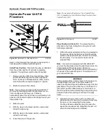
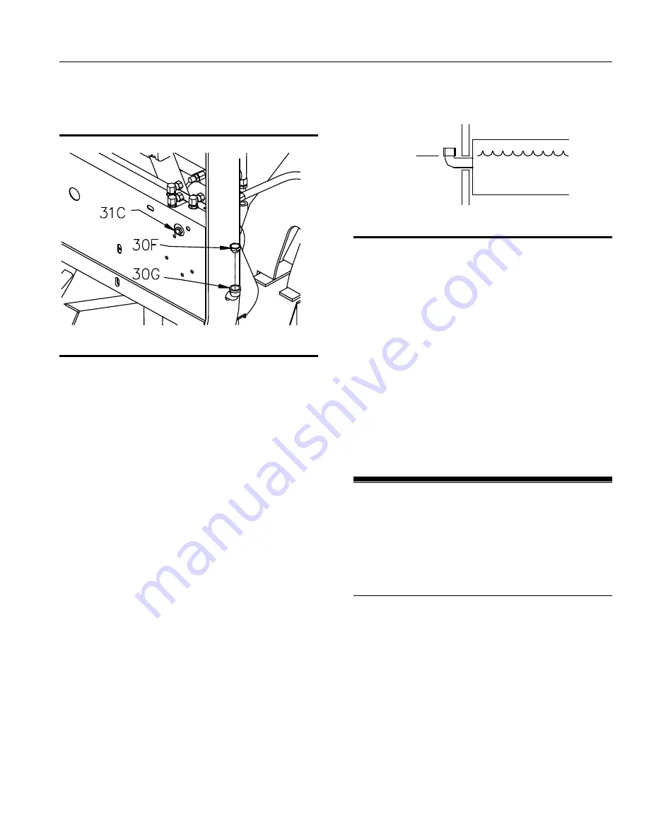
Figure 30.
External Fill – Backside View
G10043
Step 1 of the following fill procedure is intended for a
new plow with an empty hydraulic system.
Initial Plow Position:
Start with the plow un-attached
from the vehicle and the lift cylinder completely
collapsed. The light tower will be tilted forwarded.
1. Remove Fill Cap (30F) from Street Elbow (30G)
and fill with Boss High Performance Hydraulic
Fluid. Continue to fill Street Elbow (30G) until no
more fluid will be accepted. (Approx. 2 quarts.)
2. Attach the plow to the vehicle.
Note:
If your plow is equipped with SmartHitch2™
you must hydraulically power the light tower up. Do
not manually push the tower up. Failure to
hydraulically power the light tower up will create an air
pocket in the hydraulic system. Oil will spill out of your
internal filler cap.
3. Raise the plow.
4. With the plow in the raised position, extend and
retract the right wing.
5. With the plow in the raised position, extend and
retract the left wing.
6. Lower the plow to the ground.
Note:
If your plow will not lower, Flow Control Valve
(31C) is completely closed. Refer to Step 8 to adjust Flow
Control Valve (31C).
Figure 31.
Oil Full Level G10411
Plow Position to Check Oil:
The plow should be
attached to the truck, sitting flat on the ground, with
both wings retracted.
7. With both wings retracted and the plow lowered to
the ground, check the fluid level. Fluid should be
visible in the external fill port. If fluid is not visible,
fill until visible. Your reservoir should now be
properly filled.
Note:
If your plow is equipped with SmartHitch2™
you must hydraulically power the light tower down. Do
not manually pull the tower down. Failure to
hydraulically power the light tower down will create an
air pocket in the hydraulic system. Oil will spill out of
your internal filler cap.
WARNING!
When adjusting Flow Control Valve (31C) make sure
all appendages are clear of the plow blade and
observers are standing a safe distance away from the
plow blade. The plow may drop if your controller is in
the FLOAT position. Make sure your controller is in
the OFF position before attempting to adjust the plow.
Failure to follow this warning could result in bodily
harm.
8. Adjust Flow Control Valve (31C) to obtain the
speed desired for lowering the plow by loosening
the jam nut, then adjusting the set screw.
Counter-clockwise adjustment will increase the
speed the plow descends. Retighten the jam nut
when the desired speed is obtained.
FULL


