3
bossweld
.com.au
7
8
9
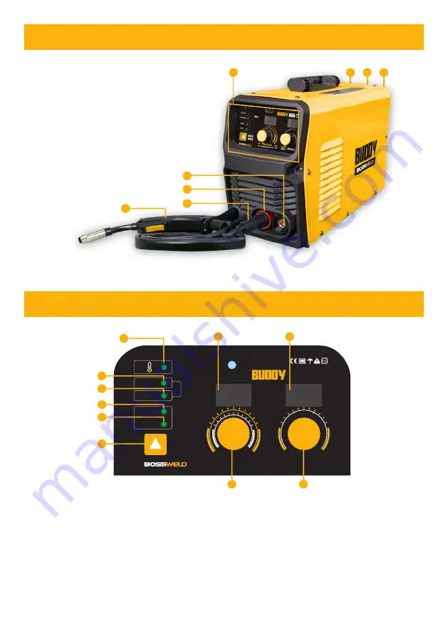
MACHINE OVERVIEW
CONTROL PANEL OVERVIEW
1. Control Panel
2. Negative Output Connection Socket
3. Positive Output Connection Socket
4. Polarity Change Power Connection
5. Direct Connect MIG Torch
6. Power Switch
(Rear of Machine)
7. Power Cable
(Rear of Machine)
8. Welding Gas Inlet
(Rear of Machine)
1. Overheat Indicator Light
2. Digital Display - Voltage
3. Digital Display - Amperage
4. Manual MIG Mode Indicator Light
5. Synergic MIG Mode Indicator Light
6. Stick Mode Indicator Light
7. VRD Indicator Light
Indicates that the Voltage Reduction Device is
operating. VRD reduces the Open Circuit Voltage
before welding for added safety
8. Process Selection Button
9. Voltage Parameter Adjustment Knob (L)
10. Current/Wire Speed Parameter Adjustment
Knob (R)
1
2
3
4
5
MIG 150
MANUAL
SYNERGIC
MMA
VRD
MIG
WELD
MODE
AMPERAGE
MIG 30
MMA 101
40
160
MANUAL VOLTAGE
15V
24V
SYNERGIC VOLTAGE TRIM
-2V
+2V
1
2
9
3
10
4
5
6
7
8


