background image

Wall-Mounting the Micro Satellites

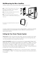
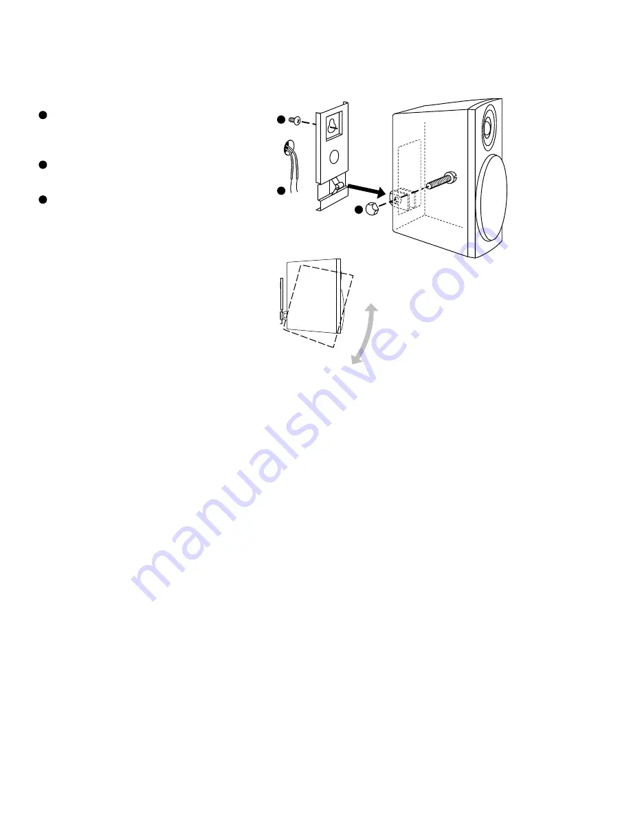
The Micro satellites may be wall-mounted using the included keyhole bracket. 

Install a #8 or #10 mounting screw on the wall (not sup-

plied–consult a knowledgeable installer regarding the

proper hardware to use on your wall).

Attach the bracket to the back of the speaker with the

machine screw and acorn nut as shown.

If you are running wires behind the wall, make a 

3

8

"

(9.5mm) wire hole, 1

3

4

" (44mm) below the mounting screw

for the wire.

The speaker may be angled for optimum coverage of the

listening area.

An optional pedestal shelf stand/wall-mount bracket (Model MRB) is available for the Micro80x

that provides greater positioning flexibility. For more information, contact your dealer or 

Boston Acoustics directly.

Setting Up Your Home Theater System

Volume Levels: 

To obtain the best home theater effect, match the sound levels of each speak-

er. Home theater systems include a test signal that simplifies this level matching. Refer to the

instructions provided with your surround sound electronics.

Center Channel Mode: 

Generally, with all surround systems, including Dolby

®

ProLogic

®

and

Dolby

®

Digital, the center channel mode should be set to “NORMAL” or “SMALL.” This setting

diverts low bass to the front left and right channels, and will result in the greatest total system

bass output. The “NORMAL” or “SMALL” center speaker setting ensures the subwoofer

receives the most bass information under all conditions. The “Phantom” setting, which presumes

you do not have a center channel speaker, should not be used.

Surround Channel Mode: 

If your electronics have a surround channel mode, it should also be

set to “NORMAL” or “SMALL.” This setting will divert any low bass in the surround channels to

the subwoofer.

1

1

2

3

2

3

Summary of Contents for Micro80x II

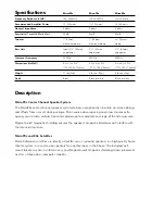
Page 1: ...System9000 The System9000 is composed of the following z VRS Micro z Micro90c z Micro90X ...

Page 2: ...Micro90c Micro90x Micro80x Micro Reference Series ...

Page 3: ...er runs Strip 1 2 12mm of insulation off the ends of each speaker cable to expose the two conductors and tightly twist the wire strands Maintain consistency of the red and black connections by using the markings on the wire IMPORTANT Typically one side of the wire is smooth Connect this side to the black con nection The other side has a rib or stripe Connect this to the red connection Using the fi...

Page 4: ...red and black connections by using the markings on the wire Placement Micro90c Center Channel Placement Place the Micro90c as close to the TV monitor as possible with its front panel flush with the front of the television Self adhesive rubber feet are included with the Micro90c to protect the TV s finish and prevent vibration Micro90x and 80x Satellite Placement For the most realistic surround eff...

Page 5: ...e Theater System Volume Levels To obtain the best home theater effect match the sound levels of each speak er Home theater systems include a test signal that simplifies this level matching Refer to the instructions provided with your surround sound electronics Center Channel Mode Generally with all surround systems including Dolby ProLogic and Dolby Digital the center channel mode should be set to...

Page 6: ... Black or white Black or white Description Micro90c Center Channel Speaker System The Micro90c center channel speaker system delivers exceptionally articulate on screen dialog and effects from a small sleek package Point source driver spacing and a low crossover fre quency assure wide uniform horizontal dispersion for complete coverage of the listening area MagnaGuard magnetic shielding ensures th...

Page 7: ...slip when requesting service Excluded from this warranty is damage that results from abuse misuse accidents shipping or repairs or modifications by anyone other than an authorized Boston Acoustics service represen tative This warranty is void if the serial number has been removed or defaced This warranty gives you specific legal rights and you may also have other rights which vary from state to st...

Page 8: ...VRS Micro Micro Reference Diffuse Field Surround Speaker System ...

Page 9: ...c rear channel surround effects with Dolby ProLogic and Dolby Digital decoding electronics The VRS Micro cabinet is sculptured to aim sound along the walls rather than directly at the listener and to blend with the room s decor Frequencies from 120 to 20 000Hz are han dled by a specially designed 31 2 89mm full range driver firing toward the front of the room Frequencies above 350Hz are handled by...

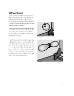
Page 10: ... sound is aimed directly at the listener Because the listener can localize the sound the surround effect is dramatically reduced above right The VRS Micro contains two drivers operating with opposite polarities one speaker pushes out and the other pulls in This directs most of the sound sideways right The VRS Micro gen erates a figure 8 pattern above 350Hz along the walls of the room The sound is ...

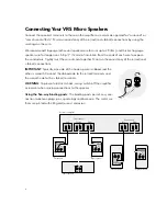
Page 11: ...ther Maintain the consistency of the red and black connections IMPORTANT Typically one side of the hook up wire is ribbed and the other is smooth Connect the ribbed side to the red terminals and the smooth side to the black terminals WARNING To prevent electrical shock always switch off the amplifier or receiver when making connections to the speaker Using the five way binding posts The binding po...

Page 12: ...ng from the ceiling Make sure the arrow on the rear label points to the front of the room If the listening position is against the wall place the speakers to either side no less than 20 50cm from the rear wall Place the VRS Micro speakers on either side of the listening area IMPORTANT Your speakers have been packed as a LEFT and RIGHT matched set Make sure that each speaker is mounted on the corre...

Page 13: ...ur electronics have a surround channel mode it should be set to Normal or Small This setting will divert any low bass in the surround channels to the subwoofer Wall or Ceiling Mounting Your VRS Micro Speakers The VRS Micro is designed to be mounted directly onto a wall or ceiling Attach the supplied bracket to the wall or ceiling and clip the speaker to the bracket You may run wires to the speaker...

Page 14: ...s the holes to be filled 1 Remove the grilles Use a small screwdriver or knife to snap open the back edge of each grille near the terminals 2 Paint the grilles Primer is not required If using a spray paint use two thin coats If using a house paint thin the paint to avoid filling the perforation holes in the grille Let the paint dry completely 3 Reinsert the grilles Insert the front edge in the gro...

Page 15: ...nty is void if the serial number has been removed or defaced This warranty gives you specific legal rights and you may also have other rights which vary from state to state If Service Seems Necessary First contact the retailer from whom you purchased the speakers If that is not possible write to Boston Acoustics Inc 300 Jubilee Drive Peabody MA 01960 We will promptly advise you of what action to t...

Reviews: