background image

2

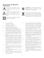
Important Safety Instructions

This symbol found on the apparatus
indicates hazards arising from danger-
ous voltages.

This symbol found on the apparatus

indicates the user should read all safety

statements found in the user manual.

This symbol found on the apparatus

indicates double insulation.

Warning! 

To reduce the risk of fire or electric

shock, do not expose this apparatus to rain or
moisture.

This symbol found on the apparatus indi-
cates that the apparatus must be placed in a
separate collection facility for electronic
waste and not disposed of with household
waste.

1.

Read these instructions.

2.

Keep these instructions.

3.

Heed all warnings.

4.

Follow all instructions.

5.

Do not use this apparatus near water.

6.

Clean only with dry cloth.

7.

Do not block any ventilation openings. Install in
accordance with the manufacturer's instructions.

8.

Do not install near any heat sources such as radi-
ators, heat registers, stoves, or other apparatus
(including amplifiers) that produce heat.

9.

Do not defeat the safety purpose of the polarized
or grounding-type plug. A polarized plug has
two blades with one wider than the other. 
A grounding type plug has two blades and a
third grounding prong. The wide blade or the
third prong are provided for your safety. If the
provided plug does not fit into your outlet,
consult an electrician for replacement of the
obsolete outlet.

10.

Protect the power cord from being walked on 
or pinched particularly at plugs, convenience
receptacles, and the point where they exit
from the apparatus.

11.

Only use attachments/accessories specified by
the manufacturer.

12.

Unplug this apparatus during lightning storms
or when unused for long periods of time.

13.

Refer all servicing to qualified service personnel.
Servicing is required when the apparatus has
been damaged in any way, such as power-sup-
ply cord or plug is damaged, liquid has been

spilled or objects have fallen into the appara-
tus, the apparatus has been exposed to rain or
moisture, does not operate normally, or has
been dropped.

14.

Maintain a minimum distance of 50 mm around
the front, rear and sides of the apparatus for 
sufficient ventilation. The ventilation should not
be impeded by covering the ventilation open-
ings or placing on or around the apparatus
items such as newspapers, table-cloths, cur-
tains, etc.

15.

No naked flame sources, such as lighted 
candles, should be placed on the apparatus.

16.

The apparatus shall not be exposed to drip-
ping or splashing.  No objects filled with liq-
uids, such as vases, shall be placed on the
apparatus.

17.

Either the power inlet connector on the rear of
the apparatus or the power plug at the wall
must remain accessible, to be able to discon-
nect power from the apparatus.

18.

To completely disconnect this apparatus from
the AC Mains, disconnect the power supply
cord plug from the AC receptacle.

19.

The mains plug of the power supply cord shall
remain readily operable.

Summary of Contents for XB6

Page 1: ...XB6 XB8 Powered Subwoofer Featuring BassTrac...

Page 2: ...he obsolete outlet 10 Protect the power cord from being walked on or pinched particularly at plugs convenience receptacles and the point where they exit from the apparatus 11 Only use attachments acce...

Page 3: ...of impressive deep bass and high output from remarkably compact enclosures In addition they feature BassTrac a proprietary Boston designed circuit that tracks the input signal to the subwoofer and pre...

Page 4: ...more information How to Connect Using the Speaker Terminals We recommend 18 gauge wire or thicker for runs up to 15 feet 4 5m and 16 gauge wire or thicker for longer runs Separate the first few inche...

Page 5: ...or XB8 jack labeled bypass crossover control underneath line level in Be sure to connect to red and to black If you do not wish to run RCA cables to your subwoofer you may use speaker wire to connect...

Page 6: ...b out connection from your receiver to the input on the subwoofer marked use crossover con trol When using speaker wire or the use crossover control input the subwoofer s built in crossover is engaged...

Page 7: ...he bass still appears to come from the main speakers In most cases the subwoofer may be placed anywhere in the listening room The level of bass output from the subwoofer will vary at different positio...

Page 8: ...T OUTPUT DIGITAL DIGITAL INPUT INPUT 6 CH INPUT 6 CH INPUT CD CD COAXIAL COAXIAL R R L L R R L L MAIN MAIN SUB SUB WOOFER WOOFER DVD DVD MD CD R MD CD R MD CD R MD CD R OPTICAL OPTICAL OPTICAL OPTICAL...

Page 9: ...XB6 XB8 Subwoofer amplificado con BassTrac...

Page 10: ...si el enchufe que se incluye no enca ja en l 10 Proteja el cable para que no pueda pisarse ni estrangularse en particular a la altura de los enchufes del tomacorriente y del punto por el que sale del...

Page 11: ...una impre sionante salida de agudos y graves profundos desde un dispositivo incre blemente compacto Adem s incluyen BassTrac un circuito patentado dise ado por Boston que realiza un seguimiento de la...

Page 12: ...e altavoz diferente V ase la p gina 8 para m s informaci n Conexi n mediante los terminales de altavoz Para longitudes de hasta 4 5 m 15 ft se recomienda un cable de calibre 18 y un calibre 16 o super...

Page 13: ...l nea Aseg rese de conectar a rojo y a negro Si no desea conectar cables RCA al subwoofer puede utilizar un cable de altavoz para conectar el subwoofer en paralelo con los alta voces principales v as...

Page 14: ...ntegrado del subwoofer En primer lugar establezca el control del separador de frecuencias del subwoofer aproximadamente 10 Hz por encima del l mite m nimo de respuesta de graves de los altavoces princ...

Page 15: ...r sigue pareciendo que los graves provienen de los altavoces principales En la mayor a de los casos el subwoofer puede colocarse en cualquier lugar de la sala donde se desee escuchar El nivel de salid...

Page 16: ...DIGITAL DIGITAL INPUT INPUT 6 CH INPUT 6 CH INPUT CD CD COAXIAL COAXIAL R R L L R R L L MAIN MAIN SUB SUB WOOFER WOOFER DVD DVD MD CD R MD CD R MD CD R MD CD R OPTICAL OPTICAL OPTICAL OPTICAL D TV CB...

Page 17: ...XB6 XB8 Caisson de graves dot de la technologie BassTrac...

Page 18: ...lectricien afin qu il remplace cette derni re devenue obsol te 10 viter de pi tiner ou pincer le cordon d alimentation particuli rement au niveau de la fiche des prises mul tiples et aux points de sor...

Page 19: ...nsi qu une puissance de sortie impressionnante partir d une enceinte exception nellement compacte Par ailleurs elles sont munies de la technologie BassTrac un circuit brevet con u par Boston qui suit...

Page 20: ...canal du haut parleur Pour plus d informa tions voir page 8 Connexion l aide des bornes du haut parleur Nous recommandons un fil de calibre 18 minimum pour des longueurs de 4 5 m 15 ft et de calibre 1...

Page 21: ...la borne sur la borne rouge et la borne la borne noire Si un acheminement des c bles RCA vers le caisson de graves n est pas souhait le fil du haut parleur peut tre utilis pour connecter le caisson e...

Page 22: ...gr du caisson de graves est activ en cas de branchement l aide du fil du haut parleur ou d utilisation de l entr e use crossover control utiliser la commande du r partiteur Pour commencer r gler le r...

Page 23: ...ipaux Dans la plupart des cas le caisson de graves peut tre positionn n importe o dans la salle d coute Le niveau de puissance des basses provenant du caisson varie en fonction de son emplacement dans...

Page 24: ...MD CD R MD CD R OPTICAL OPTICAL OPTICAL OPTICAL D TV CBL D TV CBL Y Y P PB B C CB B P PR R C CR R SURROUND SURROUND CENTER CENTER AM AM ANT ANT GND GND c ble de masse RCA RCA un conducteur panneau arr...

Reviews: