background image

Boston Gear • 800-825-6544

P-3003-BG 


13

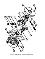
C.  Torque Verification

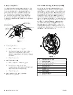
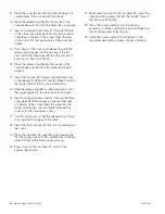
1.   Place the clutch in a chuck or vise with the cover 

facing upward.

2.   Insert the appropriate size arbor and key into rotor. 

(See Figure 18)

3.   Turn the drive spring screw (21) clockwise until it is 

flush with the surface of the housing.

4.   The clutch is supplied with a torque selector dial. 

The torque selector dial is the mill marks located at 
the hole stamped 9 on the housing. If a drive spring 
(18), reset spring (19), and/or a reset spring screw 
(14) were replaced, chances are that the stamped 
torque values on the dial are no longer valid. It may 
be necessary to grind the old numbers off and to 
stamp new ones.

5.   Tighten the reset spring screw (14) until it reaches 

the limit stop pin (4). This will be the maximum 
torque position. If the maximum torque is not 
desired, tighten the reset spring screw to one of the 
locations on the torque selector dial.

6.   Disengage the clutch with a torque wrench. Fine 

tune the torque by turning the drive spring screw 
(21) until the desired release torque is obtained.

7.   Refer to Section I, C for further details on torque 

adjustment.

8.   Once the desired release torque is obtained, tighten 

the locking screws (25) located over the drive spring 
and reset spring screws to ensure that they will not 
move. The unit is now ready for installation. Refer to 
Section lll for installation of basic clutch.

Table 10 - Cover Screw Seating Torques

Clutch  

Size

Screw Size

Quantity

Seating 

Torque

1

1/4-20

3

100 in.lb.

2

5/16-18

3

200 in.lb.

3

3/8-16

3

350 in.lb.

4

1/2-13

4

850 in.lb.

5

5/8-11

4

1,700 in.lb.

6

5/8-11

4

1,700 in.lb.

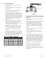
Figure 18

D.   Limit Switch Actuating Mechanism (LSAM) 

Assembly

1.   Apply a graphite lubricant to the release ring groove 

of the cover (8).

2.   Insert the actuating stud (40) through the appropriate 

hole in the release ring (35). To identify this hole 
place the release ring in the groove of the cover. 
When the trip pin holes line up with the through 
holes of the cover, the actuating stud hole will line 
up with the counterbored hole in the groove of the 
cover.

3.   Install the actuating stud nut (39) onto the actuating 

stud (40) and tighten.

4.   Install a spring terminal (43) on each end of the 

return spring (38). Clutch sizes 5 & 6 require two 
return springs.

5.   Insert a spring terminal screw (41) through the hole 

of the spring terminal (43), and place a spacer collar 
(36) on the end of the screw. Insert the end of the 
screw into the threaded hole of the release ring (35) 
and tighten. The end of the screw may protrude past 
the release ring. Grind the end of the screw flush 
with the surface of the release ring. Install second 
spring terminal screw on clutch sizes 5 & 6 as just 
described. Move to Step 13 for clutch sizes 5 & 6.

6.   Press the trip pins (32) into the trip plate (31).

7.   Install a bowed snap ring (34) into the groove of 

each trip pin located next to the trip plate.

8.   Place the trip plate flat on a table with counterbored 

holes facing up. Insert the thrust springs (37) into the 
counterbores.

Torque Wrench

Arbor

Trig-O-Matic Clutch

Vice or Chuck Jaws

Summary of Contents for ORC-S Series

Page 1: ...Installation Operation Instructions Boston Gear ORC S Series Trig O Matic Overload Release Clutches P 3003 BG ORC S Series...

Page 2: ...ive pawl and a reset pawl which are pivoted within the clutch housing The drive pawl is held engaged in the rotor notch by the combined compression of the drive and reset springs as shown in Figure 1...

Page 3: ...ich is approximately flush with the O D of the clutch housing This is essential to restore the torque to its original setting d Reducing the clutch torque setting may make the reset procedure easier i...

Page 4: ...itch Actuating Mechanism LSAM In some cases it may be necessary to adjust the actuating mechanism This is accomplished by first setting the clutch at the minimum torque settings and second disengaging...

Page 5: ...seating torques 4 Finish ream sprocket or sheave for dowel pin Refer to Table 1 for dowel pin and recommended ream sizes 5 Install dowel pins to a point where they bottom in housing B Type B Housing...

Page 6: ...37 18 37 1 875 81 3 1 25 1 62 1 94 29 50 2 750 94 4 1 56 2 12 2 37 43 56 2 828 1 48 5 1 94 2 62 3 00 58 69 4 000 1 62 6 2 62 3 50 3 87 90 87 5 500 2 00 Notes 1 The E Dimension on Table shows pawl trun...

Page 7: ...ither location of the clutch shown in Figure 11 is preferred in indirect drive applications b The mounting location in Figure 12 is not preferred for the same reasons as those for Figure 10 Always con...

Page 8: ...1 2 5 16 5 16 1 8 1 8 6 3 4 3 4 1 2 5 16 5 16 1 8 1 8 Table 6 Rotor Setscrew Seating Torques Size Screw Size Seating Torque 1 10 32 36 in lb 2 1 4 28 87 in lb 3 3 8 24 290 in lb 4 1 2 20 620 in lb 5 5...

Page 9: ...re 14 b If the difference between any two points 180 degrees apart exceeds the maximum angular misalignment shown in Table 8 the shafts must be realigned c If a correction is required to satisfy angul...

Page 10: ...mit Switch Pin A Limit Switch Pin is furnished as a standard item to activate a limit switch that triggers the electrical controls The Limit Switch Pin protrudes radially from the clutch housing and i...

Page 11: ...ing practices for the equipment on which the clutch is installed VI Repair Instructions A General Disassembly 1 All item numbers in parenthesis will refer to the key numbers shown in the clutch explod...

Page 12: ...rive spring Place one end of the drive spring over the drive spring thrust washer 22 Insert the knob of the drive pawl into the other end of the drive spring Insert the trunnion of the drive pawl into...

Page 13: ...ues Clutch Size Screw Size Quantity Seating Torque 1 1 4 20 3 100 in lb 2 5 16 18 3 200 in lb 3 3 8 16 3 350 in lb 4 1 2 13 4 850 in lb 5 5 8 11 4 1 700 in lb 6 5 8 11 4 1 700 in lb Figure 18 D Limit...

Page 14: ...first 15 Slide the release ring 35 counterclockwise so that the ring engages into the grooves of the trip pins 16 Insert a spring terminal screw 41 through the other spring terminal 43 and place a sp...

Page 15: ...Boston Gear 800 825 6544 P 3003 BG 15 NOTES...

Page 16: ...3 1 5 7 24 26 25 16 3 10 17 3 2 4 25 26 5 6 14 15 19 20 11 12 13 9 8 27 18 23 22 21 16 Boston Gear 800 825 6544 P 3003 BG ORC Series Model S with Limit Switch Pin LSAP Types SA SM...

Page 17: ...5 002 1 710355 003 1 710355 004 1 710355 005 1 710355 006 1 17 Roll Pin 040942 044 1 040942 044 1 040942 045 1 040942 045 1 040942 046 1 040942 045 1 18 Drive Spring Low Torque Range L 730385 001 1 73...

Page 18: ...18 Boston Gear 800 825 6544 P 3003 BG ORC Series Model S with Limit Switch Actuation Mechanism LSAM Types SB SC SP SS...

Page 19: ...17 2 074110 017 4 074110 017 4 42 Plate Mount Screw 730561 001 4 730561 002 4 43 Spring Terminal 730421 001 2 730421 002 2 730421 002 2 730421 002 2 730421 002 4 730421 002 4 C Coupling Ass y 710296 0...

Page 20: ...liability under this limited warranty is limited to such replacement or repair and it shall not be held liable in any form of action for direct or consequential damages to property or person THE FORE...

Reviews: