14
Boston Gear • 800-825-6544
P-3003-BG
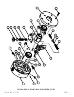
9. Place the cover (8) over the trip plate, lining up the
counterbores in the cover with the springs.
10. Place the release ring (35) into the groove of the
cover. Make sure that all of the holes line up properly.
11. Insert a spring terminal screw (41) through the hole
of the other spring terminal (43) and place a spacer
collar (36) on the end of the screw. Insert the end
of the screw into the tapped hole of the cover and
tighten.
12. Push down on the cover and release ring until the
release ring engages into the grooves of the trip
pins. Install two snap rings (33) into the grooves of
each trip pin. Move to Step 22.
13. Place the release ring (35) into the groove of the
cover. Make sure that all of the holes are properly
aligned.
14. Insert the trip pins (32) through the matching holes
in the release ring (35) and cover (8). Make sure that
the tapped hole of the trip pin is inserted first.
15. Slide the release ring (35) counterclockwise so that
the ring engages into the grooves of the trip pins.
16. Insert a spring terminal screw (41) through the other
spring terminal (43) and place a spacer collar (36)
on the end of the screw. Insert the screw into the
tapped hole in the cover and tighten. Repeat this
process for the other return spring .
17. Turn the cover over so that the release ring is facing
down against the surface of the table.
18. Insert the thrust springs (37) into the counterbores of
the cover.
19. Place the trip plate (31) over the cover making sure
that the springs will sit in the counterbores of the trip
plate and that all the holes properly line up.
20. Press down on the trip plate (31) until it stops
against the trip pins.
21. While pressing down on the trip plate (31) insert the
plate mounting screws (42) into the tapped holes of
the trip pins and tighten.
22. Press the cover assembly onto the housing
assembly (1). Make sure that the trunnion holes and
the mounting screw holes line up.
23. Install the cover screws (27) and tighten to the
recommended seating torques shown in Table 10.

