3-3
Fuel Systems
Section 3
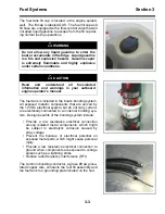
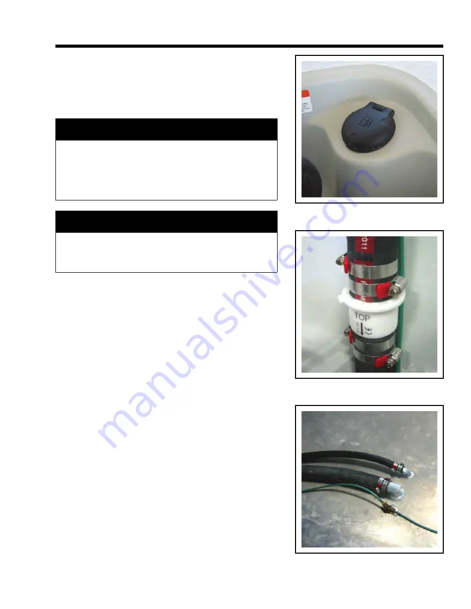
The fuel tank fill cap is located in the engine splash-
well. The fill cap is labeled GAS. The fuel fill cap and
fill hose are equipped with a flow-control valve that will
not allow liquid gasoline to escape from the fill cap dur-
ing normal fueling operations.
The fuel tank is included in the boat’s bonding system.
All exposed metallic components that are served by
the 12 VDC electrical system, but do not carry current,
are electrically connected to an internal bonding sys-
tem. Design benefits of the bonding system include:
• Provide a low resistance electrical connection
among isolated metal components, which might
be subject to electrolytic corrosion caused by
stray voltage
• Prevent the build-up of electrical potential on
exposed metal parts, which might cause personal
injury
• Provide a low resistance electrical connection to
ground when components are exposed to voltage
spikes such as a lightning strike
• Reduce radio frequency interference (RFI)
The common bonding conductor, a green #8 awg insu-
lated copper wire, connects the fuel fill assembly and
the fuel tank to a grounding plate located on the hull.
!
WARNING
Do not allow any liquid gasoline to enter the
boat or accumulate in the bilge. Liquid gasoline
is a fire and explosion hazard. Gasoline vapor
is extremely flammable and highly explosive
under certain conditions.
!
CAUTION
Read and understand all fuel-related
information and warnings in your outboard
engine operator’s manual.
Summary of Contents for 19 GuardianSeries
Page 18: ...1 10 Section 1 Safety Deck Occupancy Chart ...
Page 20: ...1 12 Section 1 Safety Warning Label Chart 1 2 3 4 5 6 7 8 9 5 0 A B D E C F ...
Page 22: ...1 14 Operator Notes ...
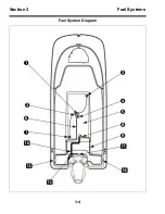
Page 56: ...3 4 Section 3 Fuel Systems Fuel System Diagram 1 C 3 2 4 5 8 9 A D B 6 7 0 ...
Page 58: ...3 6 Operator Notes ...
Page 104: ...5 10 Operator Notes ...
Page 122: ...6 8 Section 6 Boat Maintenance Trailer Setup ...
Page 133: ...6 19 Operator Notes ...
Page 134: ...6 20 Operator Notes ...

