4-38
Section 4 Boat Systems
S everal ke y points are indica ted below:
L oca te the blower switch on the AC B reake r P anel
and operate the blower for four minutes. M anually
ch eck
the bilge for fuel or fuel vapor.
Refer to the manufact urer’ s operations manual for a
pre-start ch eckl
ist.
OP E N the generator seaco ck.
E nsure the sea water strainer is cl ear.
M ake sure that AL L breake rs on the AC P anel are
switch ed OF F .
S lide the select or on the AC P anel to expose the
GE NE RATOR & B RID GE switch es.
S witch the line breake rs ON.
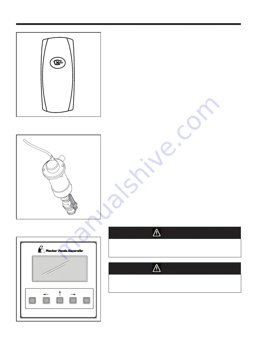
P ress the On/ Off button on the remote start panel.
The indica tor light will illuminate and the fuel gauge
will be act ivated.
P ress and release the S TART button ONL Y ONCE .
The light will begin blinki ng and the generator will
start.
After a succe
ssful start, acce
ssory breake rs ca n be
switch ed ON.
DO NO T p ress the b utton more than once.
Allow for a
6 0 sec ond co ol down period between cr anki ng attempts.
If the generator fails to start after the first attempt, ensure
adequate fuel ow and attempt start sequence again. A
major ca use of poor starting or power loss is the result of
a clogged filter element or a fuel system air leak.
AL WAY S run the b lower when op erating b elow
cruising sp eed.
U nder no circumstances override the source
select system.
DANGER
CAU T IO N
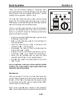
BLOWER
On/Off
Start
Stop
Alarm
Mute
Next
Screen
Set
Summary of Contents for 37 Justice Series
Page 24: ...Section 1 Safety 1 12 O p erator s Notes...
Page 56: ...Section 2 Boat O p eration 2 32 O p erator s Notes...
Page 60: ...3 4 Section 3 F uel System Diesel F uel System Diagram F O RWARD...
Page 61: ...3 5 F uel System Section 3 Gasoline F uel System Diagram F O RWARD...
Page 74: ...4 2 Section 4 Boat Systems...
Page 75: ...4 3 Boat Systems Section 4...
Page 76: ...4 4 Section 4 Boat Systems...
Page 77: ...4 5 Boat Systems Section 4...
Page 78: ...4 6 Section 4 Boat Systems...
Page 107: ...4 35 Boat Systems Section 4 F O RWARD...
Page 134: ...4 62 Section 4 Boat Systems O p erator s Notes...
Page 145: ...5 11 Electrical Systems Section 5 Main DC Breaker Panel...
Page 146: ...5 12 Section 5 Electrical Systems Main AC Breaker Panel...
Page 148: ...5 14 Section 5 Electrical Systems H elm Breaker Panel...
Page 149: ...5 15 Electrical Systems Section 5 L eaning Post Breaker Panel...
Page 150: ...5 16 Section 5 Electrical Systems Battery Switch Breaker Panel...
Page 155: ...5 21 Electrical Systems Section 5 Battery System Diagram...
Page 156: ...5 22 Section 5 Electrical Systems Battery Switch Panel Diagram...
Page 157: ...5 23 Electrical Systems Section 5 H elm Breaker Panel Diagram...
Page 158: ...5 24 Section 5 Electrical Systems H elm Switch Panel Diagram...
Page 159: ...5 25 Electrical Systems Section 5 L eaning Post Switch Panel Diagram...
Page 160: ...5 26 Section 5 Electrical Systems L ighting Schematic Deck...
Page 161: ...5 27 Electrical Systems Section 5 Windlass Schematic...
Page 162: ...5 28 Section 5 Electrical Systems O verb oard Discharge Panel and H olding T ank Schematic...
Page 163: ...5 29 Electrical Systems Section 5 DC Distrib ution Panel...
Page 164: ...5 30 Section 5 Electrical Systems DC Wiring Schematic Cab in...
Page 165: ...5 31 Electrical Systems Section 5 H ardtop Schematic...
Page 166: ...5 32 Section 5 Electrical Systems 120 0 Shore ower Schematic...
Page 167: ...5 33 Electrical Systems Section 5 AC Distrib ution Panel 120 0...
Page 168: ...5 34 Section 5 Electrical Systems 220 0 Shore ower Schematic...
Page 169: ...5 35 Electrical Systems Section 5 AC istribution anel 220 0...
Page 170: ...5 36 Section 5 Electrical Systems Bow T hruster Schematic...
Page 171: ...5 37 Electrical Systems Section 5 Bilge Wiring Schematic...
Page 172: ...5 38 Section 5 Electrical Systems Stereo Schematic...
Page 178: ...5 44 Section 5 Electrical Systems O p erator s Notes...
Page 212: ...6 34 Section 6 Maintenance Operator s Notes...
Page 214: ......

