background image

5-11

Section 5

Electrical Systems

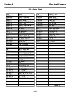
 Wire Color Chart

Black

Ground

Gray

Navigation lights

Black/brown

Ground, pumps

Gray/white

Anchor light

Black/orange

Ground, accessories

Gray/black

Masthead light

Black/green

Ground, water level sender

Gray/red

Remote spotlight

Black/blue

Ground, lighting

Gray/green

Strobe light

Black/gray

Ground, navigation lights

Gray/blue

Flood lights

Black/white

Ground, blower

Gray/orange

Docking lights

Black/white

Ground, parallel solenoid

Gray/purple

Windless

Black/white

Generator stop

Black/yellow

Engine stop

Blue

Gauge back lighting

Blue/orange

Engine room lights

Green

Bonding system

Blue/yellow

Remote lighting

Green/yellow

AC grounding

Blue/black

Dome light, T-top

Blue/black

Dome light, console

Brown

Bilge pumps, manual

Blue/red

Boarding lights

Brown/red

Bilge pumps, automatic

Blue/red

Courtesy lights

Brown/orange

Fuel transfer pumps

Blue/purple

Deck lights

Brown/white

Macerator pumps

Brown/yellow

Baitwell pumps

White

CO monitor

Brown/green

Raw water pumps

Brown/blue

Fresh water pumps

Brown/purple

Washdown pumps

Red

Battery, unprotected

Red/purple

Battery, protected

Purple

Engine, switched 12 volts

Pink

Sender, fuel level

Yellow

Bilge blower

Yellow/red

Engine start

Yellow/gray

Horn

Orange

Accessories, general

Orange/red

Wiper, port

Orange/green

Wiper, starboard

Orange/white

Wiper, center

Orange/purple

Navigation equipment

Orange/blue

Communication equipment

Orange/brown

Electric head

Orange/black

Audio system

Orange/yellow

Diesel preheat

BCGP 2013

Summary of Contents for Boston Whaler 15 Guardian Series

Page 1: ...Operation Maintenance Manual Boston Whaler 15 Guardian Series 2013 Brunswick Commercial Government Products All Rights Reserved 420 Megan Avenue Edgewater Florida 32132 USA...

Page 2: ...models or equipment but are intended as representative views for reference only The continuing accuracy of this manual cannot be guaranteed Certain features parts options systems and accessories disc...

Page 3: ...ibilities 1 1 Giving Assistance 1 1 Personal Flotation Devices 1 2 Exhaust Emissions 1 3 Fire Extinguishers 1 4 Fires 1 4 Boat Load Capacities 1 5 Capsizing 1 5 Swamping 1 6 Proposition 65 Information...

Page 4: ...ttery Parallel Switch 2 6 Starting Procedure 2 7 Shift and Throttle Control 2 8 Shifting 2 8 Neutral Throttle 2 8 Speed Control 2 9 Engine Trim 2 9 Engine Gauges 2 11 Tachometer 2 11 Water Pressure Ga...

Page 5: ...ents T 3 Section 3 Fuel Systems Safety Warnings 3 1 General Description 3 2 Racor Gasoline Filter 3 3 Fueling Procedure 3 4 Safety Warnings 3 4 Filling Portable Tank 3 5 Contaminated Gasoline 3 6 Blen...

Page 6: ...ring Effort 4 7 Navigation Lights 4 8 Operation 4 8 Bilge Pump 4 9 Operation 4 10 Compass 4 11 Deviation 4 11 Variation 4 11 Night Lighting 4 11 Battery Parallel Switch 4 12 Siren and Strobe Light 4 1...

Page 7: ...Safety Warnings 5 2 Capacities 5 3 Charging 5 4 Battery Switches 5 5 Battery Parallel Switch 5 5 Battery OFF ON Switches 5 6 Bilge Pump Special 5 6 DC Power Distribution 5 7 Outboard Engine 5 7 Bilge...

Page 8: ...ng 6 4 Gelcoat and Fiberglass Repair 6 4 Trim Care 6 5 Aluminum 6 5 Deck Hardware 6 5 Cutwater and Chafe Plates 6 6 Drains and Scuppers 6 6 Storage and Trailers 6 7 Trailer Setup 6 8 Fuel System 6 9 B...

Page 9: ...the manual particularly Sections 1 and 2 Always operate this boat within the limits of your skill and experience If you do not have the appropriate level of experience ask someone to instruct you Unde...

Page 10: ...and foul weather Type II Buoyant vest appropriate for near shore and inland waters Type III Flotation aid appropriate for calm inland waters Type IV Throwable device appropriate to throw to a person a...

Page 11: ...in confined areas such as boat houses Be aware of engine exhaust from other boats when you are moored Be aware of wind direction when operating at slow speeds Adjust hatches doors windows and canvas t...

Page 12: ...ire plan in advance that will help you evaluate your risk and response in case of an on board fire emergency Fires Most marine fires result from spilled gasoline or oil accumulating in the bilge Caref...

Page 13: ...ys responsible for the safety of the boat and its crew even if the capacity limits have not been exceeded Capsizing Your boat might capsize due to improper loading improper operation or severe weather...

Page 14: ...loading limits during emergencies special operations and severe weather Distribute any load or cargo evenly front to back and port to starboard so that the approximate cen ter of the load is near the...

Page 15: ...red by Cali fornia s Safe Drinking Water and Toxic Enforce ment Act of 1986 This hang tag outlines important information about certain chemicals known by the State of California to cause cancer and bi...

Page 16: ...1 8 Section 1 Safety Deck Occupancy Chart...

Page 17: ...lly evaluate the sea state and boat performance Restrict passenger access to these decks if conditions warrant Keep accommoda tion decks free of loose gear WARNING Gelcoat surfaces are always slippery...

Page 18: ...1 10 Section 1 Safety Warning Label Chart 1 2 4 3 5 6 7 8 9 0 A...

Page 19: ...opellers 3 1016518 Steering Effort 4 1811368 Carbon Monoxide 5 1974618 U S EPA Compliant 6 2025461 NMMA Capacity Plate 7 1795087 Proposition 65 Tag 8 1817722 Customer Information Tag 9 1016922 Battery...

Page 20: ...1 12 Operator Notes...

Page 21: ...dition Fuel filter in good condition No water in water separator Navigation lights operational Signal horn operational Bilge pump operational Bilge pump float switch operational Engine starting batter...

Page 22: ...techniques or severe operating conditions Do not use the ignition shutoff switch to stop the outboard engine during nor mal boat operation You should connect the ignition shutoff switch clip and lanya...

Page 23: ...and lanyard while the outboard engine is at idle speed The outboard engine should stop immediately The outboard engine will not start if the clip and lanyard is not attached to the shutoff switch The...

Page 24: ...ch is in the OFF position Record and save the key number following the instructions in Sec tion 6 You must turn the engine battery OFF ON switch to the ON position before you use the main engine key s...

Page 25: ...automatically If the outboard engine does not start turn the key to the OFF position and repeat the starting process To STOP the outboard engine turn the main engine key switch to the ACC or OFF posit...

Page 26: ...tch position is OFF Both the left and right switch positions are momentarily ON when held down When you release the switch it will return to the center OFF position If your outboard engine will not st...

Page 27: ...l light resis tance is felt Move engine control lever to NEUTRAL position Attach ignition shutoff switch clip and lanyard Start outboard engine using the main engine key switch Use emergency battery p...

Page 28: ...ust be running before you shift into FORWARD or REVERSE From NEUTRAL move the shift lever forward to select FORWARD gear From NEUTRAL move the shift lever backward to select REVERSE gear Never shift d...

Page 29: ...teer Trimming the engine up or out increases boat perfor mance and fuel economy Excessive trim angle will reduce boat performance Excessive trim angle might cause propeller ventilation and engine over...

Page 30: ...ngine through its trim range to change general boat operating angle Adjusting engine trim angle can affect ride com fort and boat performance 4 bow up is an average setting for boat operating angle Ad...

Page 31: ...erator s manual for detailed information about the gauges and their functions Tachometer The tachometer displays engine speed in revolutions per minute RPM You can take the gauge reading on most tacho...

Page 32: ...charges its starting battery when the engine is running above idle speed The voltmeter displays engine battery voltage measured in DC volts VDC These readings indicate that engine battery system is in...

Page 33: ...he trim gauge The trim gauge displays this value as relative Bow Up or Bow Down It takes specific experience with each boat engine pro peller combination to identify the best engine trim set tings for...

Page 34: ...ou should replace your propeller when it becomes damaged to avoid additional damage to the engine In some situations you might want to change the pro peller to give your boat slightly different perfor...

Page 35: ...of pitch change Increasing propeller pitch and diameter will decrease acceleration and might increase top speed It will also decrease the engine s full throttle RPM at a rate of about 150 RPM per inch...

Page 36: ...ple are considered part of your non permanent load Distribute any non permanent load or cargo evenly front to back and port to starboard The center of the non permanent load distribution should be in...

Page 37: ...nufacturer s instructions Center the outboard engine before tilting to avoid contact with any special towing equipment Raise the engine to full Tilt Up position and engage tilt lock Turn engine batter...

Page 38: ...ch cable tight and locked Bow safety cable attached Bow tie down link secured Stern tie down straps secured Trailer surge or electric brakes operational Trailer tires and spare in good condition Tire...

Page 39: ...ortable gasoline tank while it is in the boat Always have the portable gasoline tank on shore and connected to an appropriate grounding system before beginning your fueling procedure WARNING Your port...

Page 40: ...meet the diurnal emissions requirements outlined in ABYC Standard H24 18 4 1 and in Code of Federal Regula tions CFR Title 40 sub parts 1045 and 1060 These design elements work to limit liquid and va...

Page 41: ...to Blended Fuels in this section for more infor mation about water in gasoline Replace the filter element on this schedule whichever happens first Every 100 operating hours Annually Noticeable engine...

Page 42: ...asoline tanks are not designed to support an automatic hands free fuel nozzle Never use an automatic fuel nozzle to fill your portable gasoline tanks and never leave a fueling process unattended WARNI...

Page 43: ...e of the tank Install the fill cap and turn clockwise until the audi ble ratchet feature indicates that the cap is securely tightened CAUTION Always assume that the tank contents are under pressure wh...

Page 44: ...of gasoline that you take on board You should check the fuel fil ter sight bowl for evidence of moisture before and after every mission Refer to Blended Fuels in this section for more infor mation ab...

Page 45: ...boat Read and understand all of the fuel related safety warnings and maintenance procedures outlined in this operator manual Read and understand all of the fuel related safety warnings and maintenance...

Page 46: ...possible to reduce exposure to moisture from condensation and humidity Concentrations of ethanol greater than 10 can change the physical properties of some rubber and plastic fuel system parts such as...

Page 47: ...the most cur rent design and assembly information available at the time of publication The information and illustrations are general representations of the boat systems the information is not meant to...

Page 48: ...4 2 Section 4 Boat Systems 4 2 Section 4 Boat Systems 4 2 Section 4 Boat Systems 4 2 Section 4 Boat Systems 4 2 Section 4 Boat Systems Console Layout 1 2 3 4 5 6 7 8 9 0 B A C...

Page 49: ...on 4 1 Windshield acrylic 2 Rail hand safety 3 Compass magnetic 4 Engine instrumentation 5 Helm steering mechanical 6 Control engine single lever 7 Button horn 12 VDC 8 Panel LED battery status 9 Swit...

Page 50: ...4 4 Section 4 Boat Systems 4 4 Section 4 Boat Systems 4 4 Section 4 Boat Systems 4 4 Section 4 Boat Systems 4 4 Section 4 Boat Systems Deck Layout 1 2 3 4 5 7 6 8 9 0 A...

Page 51: ...Boat Systems Section 4 4 5 Boat Systems Section 4 1 Bow chock assembly 2 Cleat bow 3 Locker bow storage 4 Console control 5 Storage battery engine 6 Pilot seat reversible 7 Tank portable gasoline 8 Pu...

Page 52: ...by the steering clutch system and they can be felt during a course change If you have not operated a no feedback cable steer ing system it is very important that you understand its capabilities and it...

Page 53: ...aking course changes but it does not eliminate the steering torque loads When the boat is on plane you might feel a significant difference in steering effort during a course change to port or to starb...

Page 54: ...lights are in working condition and that proper lighting is displayed Operation Operate your navigation lights using the switch located on the helm station switch panel It is a three position rocker s...

Page 55: ...ne battery OFF ON switch The bilge pump system has an uninterruptible supply of power that is not affected by the position of the engine battery OFF ON switch The uninterruptible bilge pump power circ...

Page 56: ...running The MANUAL switch position provides power directly to the bilge pump When the rocker switch is in the MANUAL position the bilge pump will run even if there is no water in the bilge The rocker...

Page 57: ...r to the compass manufacturer s literature for detailed information about the compensation proce dure Variation It is important to understand that magnetic compasses point toward magnetic north There...

Page 58: ...posi tion rocker switch that is ON OFF ON The center switch position is OFF Both the left and right switch positions are momentarily ON when held down When you release the switch it will return to the...

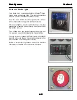
Page 59: ...e the various strobe radio siren and public address features The siren amplifier circuit is protected by a 10 amp blade fuse located in the accessory fuse block inside the control console Turn off the...

Page 60: ...tery Status Indicator Your boat is equipped with a battery status indicator panel The panel is mounted on the control console face The panel has a green LED that is lighted any time a battery switch o...

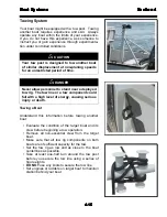
Page 61: ...re beginning a tow operation Remove all non essential crew from the target boat Make sure that all tow rig components on both boats are of sufficient capacity for the tow Set the tow rig as low and as...

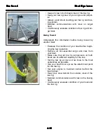
Page 62: ...this information before being towed by another boat Evaluate the condition of your boat before begin ning the tow operation Remove all non essential cargo and crew from your boat Make sure that all to...

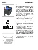
Page 63: ...outboard engine is running above idle speed regardless of battery OFF ON switch position Each electrical circuit is configured as a two wire neg ative return system which includes a 12 VDC power lead...

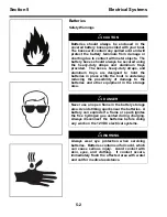
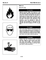
Page 64: ...in place while the boat is underway reducing the possibility of damage to the batteries and other equipment in the storage area DANGER Never use an open flame in the battery storage area Avoid striki...

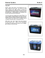
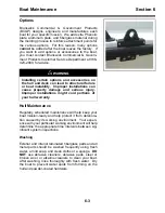
Page 65: ...batteries are considered wet cell and require periodic maintenance Your boat might be equipped with Optima Blue Top marine batteries Optima batteries use spiral cell tech nology to improve vibration...

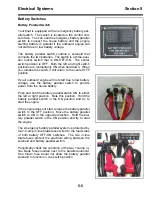
Page 66: ...discharging into a lower charged bat tery 2 by keeping the batteries electrically isolated If a battery fails to accept a charge from the engine alternator check the following items before replacing...

Page 67: ...attery voltage use the battery parallel switch to provide power from the house battery Push and hold the battery parallel switch ON to either the left or right position Note this position Hold the bat...

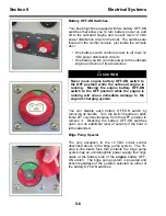
Page 68: ...ockwise from the OFF position to remove it Disabling the battery OFF ON switches gives you an additional level of security if the boat is left unattended Bilge Pump Special The only exception to the 1...

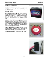
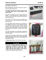
Page 69: ...tery OFF ON switch is located in the control console just inside the console door The main power and negative cables from the out board engine route through the splash well boot and connect to this po...

Page 70: ...less of switch position The circuit is protected by one 15 amp in line blade fuse located within seven inches of the outboard engine battery OFF ON switch If the 15 amp blade fuse fails electrically t...

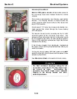
Page 71: ...m Any accessories installed on these switches must also connect to the negative side of the 12 VDC electrical system through the negative terminal strip provided One negative terminal strip is located...

Page 72: ...use block The accessory fuse block also has ten connection points for the negative side of the 12 VDC electrical system Some of the electrical accessories might have been installed at the factory If t...

Page 73: ...en yellow AC grounding Blue black Dome light T top Blue black Dome light console Brown Bilge pumps manual Blue red Boarding lights Brown red Bilge pumps automatic Blue red Courtesy lights Brown orange...

Page 74: ...5 12 Operator Notes...

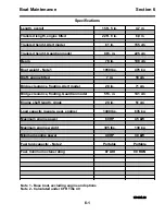
Page 75: ...7 in 18 cm Bridge clearance floating Alert model 28 in 71 cm Bridge clearance floating Guardian model 55 in 141 cm Engine shaft length single 20 in 51 cm Load capacity people gear engine 1400 lbs 635...

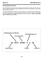
Page 76: ...ed to your boat The engine and electronics model and serial numbers are also important when obtaining parts or service for these items Record all significant numbers for HIN keys engines capital equip...

Page 77: ...rom deteriora tion caused by its working environment Your experi ence with your particular working environment will help determine the appropriate time intervals between sig nificant system inspection...

Page 78: ...cleaned to remove all dirt and oil Use a fine grade compound formulated for gelcoat and fiberglass parts Follow the manufacturer s instructions carefully After compounding re wax all surfaces followi...

Page 79: ...items can be cleaned with a mild soap and a soft cloth or sponge Aluminum Wash aluminum parts with clear water and mild deter gent Protect surface with liquid cleaner or wax DO NOT use harsh chemicals...

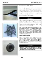
Page 80: ...but sometimes the powder coat might be worn or chipped away If the powder coat gets chipped away touch up the part with a high quality acrylic enamel Drains and Scuppers Check all compartment drains s...

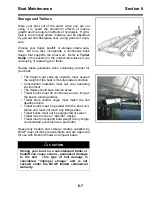
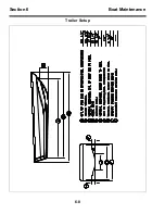
Page 81: ...ully loaded condition Construction materials must suit your operating environment The trailer should have torsion axles Trailer bunks must be continuous and as long as the boat s running surface Trail...

Page 82: ...6 8 Section 6 Boat Maintenance Trailer Setup...

Page 83: ...ction and servicing routine is directly related to the quality and quantity of gasoline that you take on board You should check the sight bowl for evidence of moisture before and after every mission R...

Page 84: ...in place while the boat is underway reducing the possibility of damage to the batteries and other equipment in the storage area DANGER Never use an open flame in the battery storage area Avoid striki...

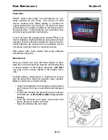
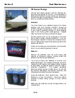
Page 85: ...quire periodic checks of electrolyte levels With proper care these marine heavy duty batteries will last several years Maintenance Only use elastic lock nuts with flat washers or stan dard hex nuts wi...

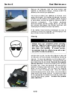
Page 86: ...have dirt or corrosion on the terminals the batteries should be cleaned To clean the batteries turn the battery OFF ON switches to the OFF position Disconnect the bat tery cables from the terminals R...

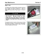
Page 87: ...he pump Periodically check the condition of the pump by turning the pump on manually You should see it pump water out the through hull fitting if there is water in the bilge or hear the pump motor run...

Page 88: ...oce dure for adding extra internal lubrication just before the engines are stored Follow all the storage and winterization recommenda tions in your outboard operator s manual Batteries Remove the batt...

Page 89: ...asis or just before storing your boat Store your boat with the fuel tanks full to avoid exposing the fuel to moisture in the atmosphere Refer to Filling Portable Tank in Section 3 of this manual for f...

Page 90: ...6 16 Operator Notes...
Page 91: ...ble and proper maintenance negligence or accident The obligation of BCGP under this warranty is limited to the pro rata cost to repair or replace a hull or part that has within the warranty period bee...

Page 92: ...World class support for World class boats...

Reviews: