3-14
345 Conquest
Section 3 • Systems & Components Overview & Operation
R
Maintenance
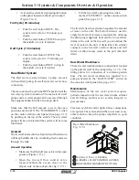
Very little maintenance is required for the freshwater
system, other than annual disinfecting and winterizing.
Periodically inspect to assure hose connections, tube
fittings, electrical connections and mounting bolts are
properly secured, and free of chafing. Periodically
check the in-line strainer attached to the pump, and
clean if necessary.
The system should be run at
least every other month to
maintain the pump’s impellers
in a stable operating condition.
Winterizing The System
If the water system will not
be used for an extended amount of time it is
recommended that it be drained. Draining the
freshwater system will require you to energize the
freshwater pump switch on the instrument panel,
press the button on the freshwater shower head
and empty the freshwater tank. Next disconnect
the hoses to and from the water pump to allow as
much water as possible to drain out. De-energize
the fresh water pump switch. Some service facilities
may recommend filling the freshwater system with
a non-toxic, non-freezing solution. This procedure
should be completed by an authorized service center.
NOTICE
As a precaution against accidental flooding.
Remove the hose when leaving the boat for an
extended period of time.
Water Heater
Make sure the fresh water tank is full before
operating the water heater. Operating water
heater empty will cause damage to system.
NOTICE
Hydrogen gas may form in the tank if the
system has not been used for more than two
weeks. DO NOT smoke or have any flame near
an open faucet.
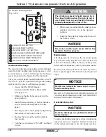
!
WARNING
SCALDING INJURY - Turn OFF the water heater
and wait for the water in the storage tank to
cool before opening the drain valve to flush
the tank.
!
CAUTION
Operation
Make sure the “FRESH WATER” switch (See fig.
4.7.1) on the DC Breaker Panel located on the port
gunnel is “ON” before energizing the water heater
(See fig. 4.8.1).
The water heater is equipped with a temperature
and pressure relief valve that complies with the
standard for Relief Valves & Automatic Gas Shut
off Devices for Hot Water Systems, ANSI Z 21.22
NOTICE
W
AR
ME
R COLD
ER
130
F
100
F
O
O
1
2
3
4
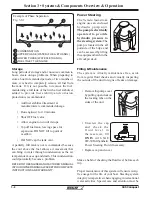
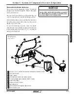
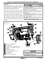
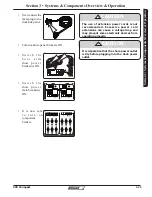
11 GAL (41.64 L) WATER HEATER
RELIEF VALVE
WATER INLET (FROM WATER TANK)
DRAIN
COLD WATER LINE
HOT WATER LINE
TEMPERING (MIXING) VALVE
WATER OUTLET (TO HOT WATER LINES)
1
2
3
4
5
Water Heater
Fig. 3.14.1
6
5
6
7
8
7
8
Turn “ON” the “WATER HEATER” switch on the
AC Main Distribution Panel (See fig. 4.8.1). Once
both the “FRESH WATER” switch and the “WATER
HEATER” switches are “ON” the system can be
utilized.
NOTE:
If the water heater has not been used for
some time it will take approximately 20 minutes for
the water to heat.
Summary of Contents for CONQUEST 345
Page 21: ...xix 345 Conquest THIS PAGE INTENTIONALLY LEFT BLANK...
Page 93: ...2 46 Section 2 General Information 345 Conquest THIS PAGE INTENTIONALLY LEFT BLANK...
Page 150: ...4 16 345 Conquest Section 4 Electrical System Batteries Joystick Steering Option Fig 4 16 1...
Page 152: ...4 18 345 Conquest Section 4 Electrical System DC MDP Joystick Steering Fig 4 18 1...
Page 154: ...4 20 345 Conquest Section 4 Electrical System AC Power 220V 50Hz Fig 4 20 1...
Page 156: ...4 22 345 Conquest Section 4 Electrical System Cabin O H and Accent Lights Fig 4 22 1...
Page 158: ...4 24 345 Conquest Section 4 Electrical System Wipers and Washers Fig 4 24 1...
Page 160: ...4 26 345 Conquest Section 4 Electrical System Waste System Fig 4 26 1...
Page 161: ...4 27 Section 4 Electrical System 345 Conquest Section 4 Electrical System Windlass Fig 4 27 1...
Page 162: ...4 28 345 Conquest Section 4 Electrical System Trim Tabs Fig 4 28 1...
Page 166: ...4 32 345 Conquest Section 4 Electrical System Pumps Sheet 2 Fig 4 32 1...
Page 168: ...4 34 345 Conquest Section 4 Electrical System V Berth Schematic Fig 4 34 1...
Page 170: ...4 36 345 Conquest Section 4 Electrical System Shore Power 230V 50HZ Fig 4 36 1...
Page 172: ...4 38 345 Conquest Section 4 Electrical System Stereo Premium Option Fig 4 38 1...
Page 174: ...4 40 345 Conquest Section 4 Electrical System Heater CO Monitor Fig 4 40 1...
Page 176: ...4 42 345 Conquest Section 4 Electrical System Generator 230V 50Hz Fig 4 42 1...
Page 178: ...4 44 345 Conquest Section 4 Electrical System STBD AC Harness Fig 4 42 1...
Page 180: ...4 46 345 Conquest Section 4 Electrical System STBD DC Harness Fig 4 44 1...
Page 182: ...4 48 345 Conquest Section 4 Electrical System Windlass Harness Fig 4 46 1...
Page 206: ...5 22 Section 5 Care Maintenance 345 Conquest THIS PAGE INTENTIONALLY LEFT BLANK...


