3-15
345 Conquest
Section 3 • Systems & Components Overview & Operation
Section 3 • Systems & Components Overview & Operation
345 Conquest
R
Section 3 • Systems & Components Overview & Operation
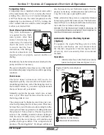
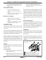
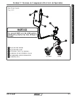
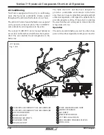
Tempering Valve
A tempering valve is installed on the hot water outlet
of the water heater (Fig. 3.16.1) to reduce the risk of
scalding. The valve is set at it’s lowest temperature
(100°F) at the factory. The water temperature can be
adjusted up to a maximum of 130°F by turning the
valve counterclockwise until the water temperature
reaches your desired limit.
REFER TO THE MANUFACTURER’S MANUAL IN
YOUR OWNER’S MANUAL PACKET FOR COMPLETE
INSTRUCTIONS AND WARRANTY.
Fresh Water System Maintenance
Very little maintenance
is required for the fresh
water system, other than
annual disinfecting and
winterizing. Periodically
check the entire system
to assure that the hose
connections, tube fittings,
electrical connections and
mounting bolts are properly secured, and free of
chafing.
Periodically check the in-line strainer attached to the
pump, and clean if necessary.
The system should be run at least every other month
to maintain the pump’s impellers in a stable operating
condition.
Maintenance
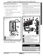
The water heater connections will need to be
inspected regularily. Access to the water heater can be
made through the back wall of the hanging closet in
the forward console. If you notice any leaks around
the water heater call your dealer.
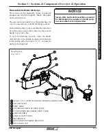
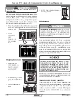
Manually operate the pressure relief valve at least
once a year. This must be done when the water in
the storage tank is cool.
The system must be flushed several times per year;
which will prolong the life of the system. There may
be times that you will notice an odor coming from the
water system. There is a protective cladding in the tank
that protects it from corrosion. The electro-galvanic
action of the cladding material releases hydrogen
from the water. If sulfur or any of its combinations
are present in the water the two will combine and
produce hydrogen sulfide. This compound will
produce a “Rotten Egg Odor”. Hydrogen sulfide can
also be present in your freshwater supply. It is the
product of the decay of animal matter and as little as
1 mg/liter can cause a perceptible odor.
Make certain that the system is completely drained
before laying up for the winter season. The freshwater
tank will have to be drained and flushed with a non-
toxic anti-freeze before winter storage.
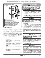
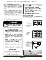
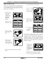
If equipped, the engine flushing system is fully
automatic and flushes salt and minerals from
the internal components of marine engines more
effectively and conveniently than conventional
methods.
Operation
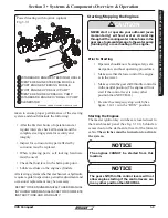
• Attach a water hose to the fresh water intake
located on the port transom (Figure 3.14.1).
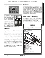
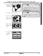
Automatic Engine Flushing System
(Option)
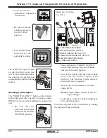
ENG FLUSH
OPERATION
FULL CYCLE (15 MIN/ENG):
PRESS ONCE TO START
PRESS TWICE TO STOP
HALF CYCLE (7.5 MIN/ENT):
PRESS TWICE TO START
PRESS ONCE TO STOP
Engine Flush System (Option)
Fig. 3.15.1
1
2
ENGINE FLUSH PANEL
FRESH WATER INTAKE
1
2
Summary of Contents for CONQUEST 345
Page 21: ...xix 345 Conquest THIS PAGE INTENTIONALLY LEFT BLANK...
Page 93: ...2 46 Section 2 General Information 345 Conquest THIS PAGE INTENTIONALLY LEFT BLANK...
Page 150: ...4 16 345 Conquest Section 4 Electrical System Batteries Joystick Steering Option Fig 4 16 1...
Page 152: ...4 18 345 Conquest Section 4 Electrical System DC MDP Joystick Steering Fig 4 18 1...
Page 154: ...4 20 345 Conquest Section 4 Electrical System AC Power 220V 50Hz Fig 4 20 1...
Page 156: ...4 22 345 Conquest Section 4 Electrical System Cabin O H and Accent Lights Fig 4 22 1...
Page 158: ...4 24 345 Conquest Section 4 Electrical System Wipers and Washers Fig 4 24 1...
Page 160: ...4 26 345 Conquest Section 4 Electrical System Waste System Fig 4 26 1...
Page 161: ...4 27 Section 4 Electrical System 345 Conquest Section 4 Electrical System Windlass Fig 4 27 1...
Page 162: ...4 28 345 Conquest Section 4 Electrical System Trim Tabs Fig 4 28 1...
Page 166: ...4 32 345 Conquest Section 4 Electrical System Pumps Sheet 2 Fig 4 32 1...
Page 168: ...4 34 345 Conquest Section 4 Electrical System V Berth Schematic Fig 4 34 1...
Page 170: ...4 36 345 Conquest Section 4 Electrical System Shore Power 230V 50HZ Fig 4 36 1...
Page 172: ...4 38 345 Conquest Section 4 Electrical System Stereo Premium Option Fig 4 38 1...
Page 174: ...4 40 345 Conquest Section 4 Electrical System Heater CO Monitor Fig 4 40 1...
Page 176: ...4 42 345 Conquest Section 4 Electrical System Generator 230V 50Hz Fig 4 42 1...
Page 178: ...4 44 345 Conquest Section 4 Electrical System STBD AC Harness Fig 4 42 1...
Page 180: ...4 46 345 Conquest Section 4 Electrical System STBD DC Harness Fig 4 44 1...
Page 182: ...4 48 345 Conquest Section 4 Electrical System Windlass Harness Fig 4 46 1...
Page 206: ...5 22 Section 5 Care Maintenance 345 Conquest THIS PAGE INTENTIONALLY LEFT BLANK...

