3-28
345 Conquest
Section 3 • Systems & Components Overview & Operation
R
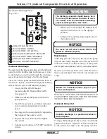
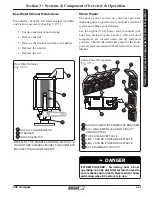
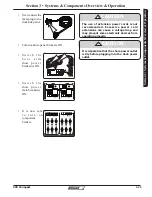
The shore power system on your boat includes an
ELCI (Equipment Leakage Circuit Interrupter)
located on the aft starboard freeboard (See figure
3.29.1).
The ELCI is designed to protect people from line-
to-ground shock hazards which may occur from
defective, misused or neglected electrical equipment.
The ELCI will not prevent line-to-ground electric
shock, but does limit the time of exposure to a
period considered safe for normal healthy persons.
If an imbalance of current is sensed, the ELCI will
trip when the ground fault exceeds 0.030 amps.
This tripping action will occur within a fraction of a
second to prevent serious injury.
ELCI
(Equipment Leakage Circuit Interrupter)
The receptacle will not protect against line-to-
line or line-to-neutral faults, short circuits or
overloads.
!
DANGER
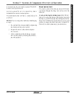
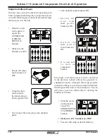
TESTING & TROUBLESHOOTING
TEST BEFORE EACH USE
NORMAL OPERATING STATE
- Sensing
device GREEN LED is ON and circuit breaker
is at ON position.
Step 1
- Press TEST button. GREEN LED
should go OUT and RED LED should come
ON and circuit breaker should trigger to OFF
position.
Step 2 -
If sensing device LED or breaker
does not trip or change state DO NOT USE.
Consult an electrician for assistance.
Step 3
- Press RESET button. The RED LED
should turn OFF and the GREEN LED should
turn ON.
Step 4
- Manually reset (switch) circuit
breaker to ON position to restore circuit
power.
WARNING
IF ABOVE TESTS FAIL,
DO NOT USE
.
CONSULT A QUALIFIED ELECTRICIAN FOR
REPAIR OR REPLACEMENT.
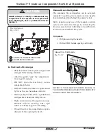
• Be certain that the shore power main
switch is turned OFF before connecting the
power cord cordset.
• Connect the cordset to the boat inlet first,
then to the shore inlet.
• NEVER alter the cordset connectors.
!
CAUTION
!
CAUTION
Shore power cords should be secured or routed
to avoid laying or falling into water and to avoid
stress on shore power plug and inlet.
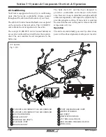
Shore Power Operation
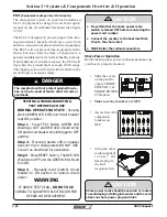
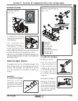
Before making shore power connections make sure
your boat is properly moored.
• Slide the covers
on the panel to
expose SHORE
POWER # 1 &
SHORE POWER
#2 breakers.
• Make sure the breakers are OFF.
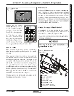
• Assure that ALL
component
breakers are
OFF.
• Using the shore
cords, (supplied)
c o n n e c t t h e
female plug to
the boat
receptacle first.
OFF
OFF
OFF
OFF
OFF
OFF
OFF
OFF
OFF
OFF
OFF
OFF
MAIN
GENERATOR
AFT
CHARGER
FWD
CHARGER
WATER
HEATER
COCKPIT
OUTLETS
COCKPIT
REFRIG
COCKPIT
A/C
COCKPIT
FREEZER
GRILL
STOVE
OFF
OFF
OFF
OFF
OFF
OFF
CABIN
OUTLETS
CABIN
REFRIG
CABIN
A/C
SHORE POWER 1
REVERSE
SHORE POWER 2
REVERSE
MAIN
GEN BRIDGE
120 V AC
BLOWER
WARNING!
GASOLINE VAPORS
CAN EXPLODE
BEFORE STARTING
GENERATOR:
CHECK FOR GASOLINE
VAPORS
OPERATE BLOWER
FOR 4 MINUTES
OFF
OFF
OFF
OFF
OFF
OFF
OFF
OFF
OFF
OFF
OFF
OFF
MAIN
GENERATOR
AFT
CHARGER
FWD
CHARGER
WATER
HEATER
COCKPIT
OUTLETS
COCKPIT
REFRIG
COCKPIT
A/C
COCKPIT
FREEZER
GRILL
STOVE
OFF
OFF
OFF
OFF
OFF
OFF
CABIN
OUTLETS
CABIN
REFRIG
CABIN
A/C
SHORE POWER 1
REVERSE
SHORE POWER 2
REVERSE
MAIN
GEN BRIDGE
120 V AC
BLOWER
WARNING!
GASOLINE VAPORS
CAN EXPLODE
BEFORE STARFTING
GENERATOR:
CHECK FOR GASOLINE
VAPORS
OPERATE BLOWER
FOR 4 MINUTES
START
STOP
MODE
KOHLER
OFF
OFF
Summary of Contents for CONQUEST 345
Page 21: ...xix 345 Conquest THIS PAGE INTENTIONALLY LEFT BLANK...
Page 93: ...2 46 Section 2 General Information 345 Conquest THIS PAGE INTENTIONALLY LEFT BLANK...
Page 150: ...4 16 345 Conquest Section 4 Electrical System Batteries Joystick Steering Option Fig 4 16 1...
Page 152: ...4 18 345 Conquest Section 4 Electrical System DC MDP Joystick Steering Fig 4 18 1...
Page 154: ...4 20 345 Conquest Section 4 Electrical System AC Power 220V 50Hz Fig 4 20 1...
Page 156: ...4 22 345 Conquest Section 4 Electrical System Cabin O H and Accent Lights Fig 4 22 1...
Page 158: ...4 24 345 Conquest Section 4 Electrical System Wipers and Washers Fig 4 24 1...
Page 160: ...4 26 345 Conquest Section 4 Electrical System Waste System Fig 4 26 1...
Page 161: ...4 27 Section 4 Electrical System 345 Conquest Section 4 Electrical System Windlass Fig 4 27 1...
Page 162: ...4 28 345 Conquest Section 4 Electrical System Trim Tabs Fig 4 28 1...
Page 166: ...4 32 345 Conquest Section 4 Electrical System Pumps Sheet 2 Fig 4 32 1...
Page 168: ...4 34 345 Conquest Section 4 Electrical System V Berth Schematic Fig 4 34 1...
Page 170: ...4 36 345 Conquest Section 4 Electrical System Shore Power 230V 50HZ Fig 4 36 1...
Page 172: ...4 38 345 Conquest Section 4 Electrical System Stereo Premium Option Fig 4 38 1...
Page 174: ...4 40 345 Conquest Section 4 Electrical System Heater CO Monitor Fig 4 40 1...
Page 176: ...4 42 345 Conquest Section 4 Electrical System Generator 230V 50Hz Fig 4 42 1...
Page 178: ...4 44 345 Conquest Section 4 Electrical System STBD AC Harness Fig 4 42 1...
Page 180: ...4 46 345 Conquest Section 4 Electrical System STBD DC Harness Fig 4 44 1...
Page 182: ...4 48 345 Conquest Section 4 Electrical System Windlass Harness Fig 4 46 1...
Page 206: ...5 22 Section 5 Care Maintenance 345 Conquest THIS PAGE INTENTIONALLY LEFT BLANK...


