3-37
345 Conquest
Section 3 • Systems & Components Overview & Operation
Section 3 • Systems & Components Overview & Operation
345 Conquest
R
Section 3 • Systems & Components Overview & Operation
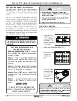
Anchor Windlass
Use the windlass switch on the helm whenever
possible. Use care when operating the anchor
windlass with the hand-held remote.
!
DANGER
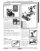
The anchor windlass located at the bow gives you
a mechanical means of raising and lowering the
anchor.
The anchor windlass is controlled by switches located
on the Control station switch panel or by a hand held
remote located in the bow locker.
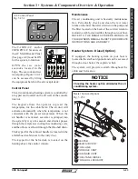
The ON/OFF switch on the control station switch
panel controls power to the windlass.
The operation switch is a momentary type switch
which means that there must be constant pressure
applied to the switch to operate the anchor windlass.
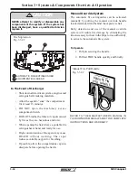
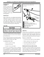
When not in use, the remote can be stored in a
receptacle located on the bulkhead of the bow locker.
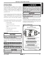
The power source for the remote is also located in
the locker (See fig. 3.35.1).
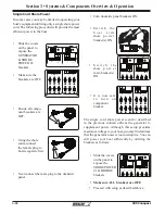
There is also a handle that can be used to raise and
lower the anchor manually in case the power to the
anchor windlass is lost.
A anchor lanyard secures the anchor when stowed
and the boat is underway.
The windlass is protected by a 100 amp circuit
breaker located on the battery switch panel (See page
4-5). If there is a loss of power to the windlass, check
the “WINDLASS” circuit breaker. If the breaker is
tripped, reset the breaker.
If the breaker continues to trip, have the anchor
windlass system checked by a qualified marine
electrician.
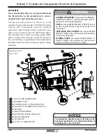
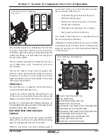
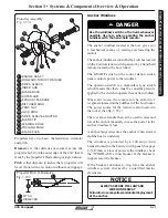
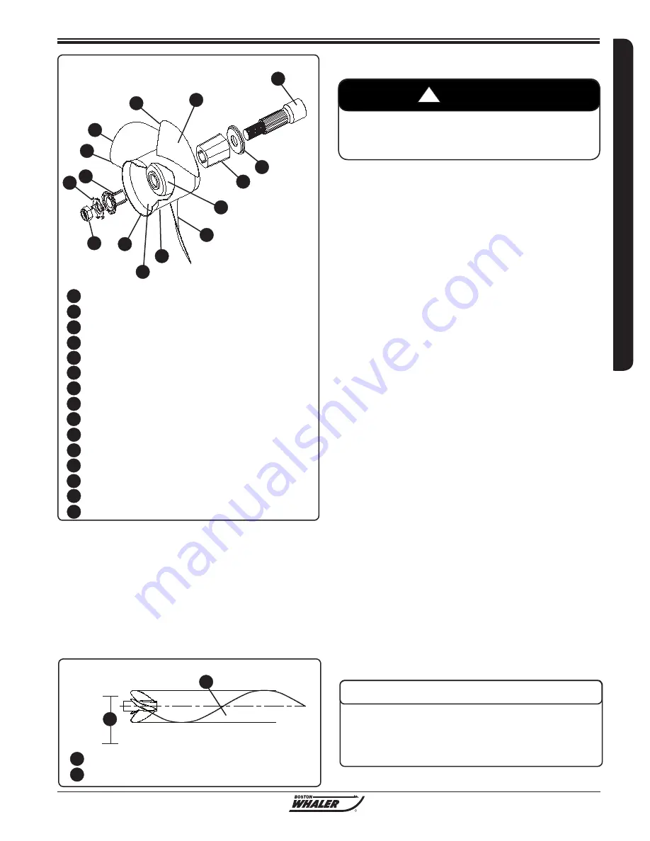
Propeller Assembly
Fig. 3.37.1
1
2
3
4
5
6
7
8
ENGINE SHAFT
FORWARD THRUST WASHER
DRIVE SLEEVE
INNER HUB
BLADE BACK
OUTER HUB
EXHAUST PASSAGE
DIFFUSER RING
PROP NUT
LOCK RING
DRIVE SLEEVE ADAPTER
BLADE TIP
LEADING EDGE
TRAILING EDGE
BLADE FACE
9
1
2
3
4
5
6
7
8
9
10 11
12
13
14
15
10
11
12
13
14
15
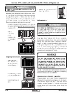
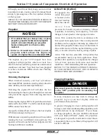
Propellers have two basic characteristics, diameter
and pitch.
Diameter
is that distance measured across the
propeller hub from the outer edge of the 360
o
that is
made by the propeller’s blade during a single rotation.
Pitch
is that distance in inches that a propeller will
travel if rotated one revolution without any slippage.
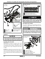
Propeller Pitch & Diameter
Fig. 3.37.2
PITCH
DIAMETER
1
2
1
2
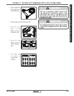
NOTICE
ALWAYS SECURE THE LANYARD
WHEN UNDERWAY
Failure to do so may allow accidental deployment
of the anchor.
Summary of Contents for CONQUEST 345
Page 21: ...xix 345 Conquest THIS PAGE INTENTIONALLY LEFT BLANK...
Page 93: ...2 46 Section 2 General Information 345 Conquest THIS PAGE INTENTIONALLY LEFT BLANK...
Page 150: ...4 16 345 Conquest Section 4 Electrical System Batteries Joystick Steering Option Fig 4 16 1...
Page 152: ...4 18 345 Conquest Section 4 Electrical System DC MDP Joystick Steering Fig 4 18 1...
Page 154: ...4 20 345 Conquest Section 4 Electrical System AC Power 220V 50Hz Fig 4 20 1...
Page 156: ...4 22 345 Conquest Section 4 Electrical System Cabin O H and Accent Lights Fig 4 22 1...
Page 158: ...4 24 345 Conquest Section 4 Electrical System Wipers and Washers Fig 4 24 1...
Page 160: ...4 26 345 Conquest Section 4 Electrical System Waste System Fig 4 26 1...
Page 161: ...4 27 Section 4 Electrical System 345 Conquest Section 4 Electrical System Windlass Fig 4 27 1...
Page 162: ...4 28 345 Conquest Section 4 Electrical System Trim Tabs Fig 4 28 1...
Page 166: ...4 32 345 Conquest Section 4 Electrical System Pumps Sheet 2 Fig 4 32 1...
Page 168: ...4 34 345 Conquest Section 4 Electrical System V Berth Schematic Fig 4 34 1...
Page 170: ...4 36 345 Conquest Section 4 Electrical System Shore Power 230V 50HZ Fig 4 36 1...
Page 172: ...4 38 345 Conquest Section 4 Electrical System Stereo Premium Option Fig 4 38 1...
Page 174: ...4 40 345 Conquest Section 4 Electrical System Heater CO Monitor Fig 4 40 1...
Page 176: ...4 42 345 Conquest Section 4 Electrical System Generator 230V 50Hz Fig 4 42 1...
Page 178: ...4 44 345 Conquest Section 4 Electrical System STBD AC Harness Fig 4 42 1...
Page 180: ...4 46 345 Conquest Section 4 Electrical System STBD DC Harness Fig 4 44 1...
Page 182: ...4 48 345 Conquest Section 4 Electrical System Windlass Harness Fig 4 46 1...
Page 206: ...5 22 Section 5 Care Maintenance 345 Conquest THIS PAGE INTENTIONALLY LEFT BLANK...

