background image

4-9

345 Conquest

Section 4 • Electrical System

345 Conquest

Section 4 • Electrical System

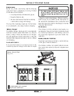
There are electronic fuse blocks 

located behind the breaker panel 

in the aft starboard cabin and, if 

equipped, in the upper control 

station.
In the event you need to replace 

a fuse, use only the same 

amperage as the original. It is recommended that 

you carry spare fuses.
If a fuse is replaced with one of lower amperage, it 

will not be sufficient to carry the electrical load of the 

equipment it is connected to and will cause nuisance 

fuse failure or breaker tripping.

If a fuse is replaced with one of higher amperage, 

it will not provide adequate protection against an 

electrical malfunction and will create a fire hazard.


Fuse Blocks

Use of higher amperage fuses or breakers is a 

fire hazard.

Use fuses and breakers having the same 

amperage rating as the original or as specified.

!

WARNING

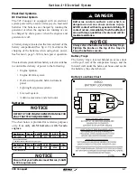
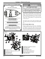
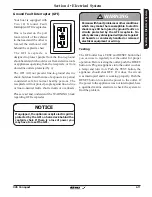
12 Volt Accessory Receptacles

Your boat is equipped with six (6)     

12 volt receptacles:

  •  Control station
  •  Starboard helm in the    

    lockable glove box

  •  Storage box in the port lounge 
  •  Forward wall of the hanging closet in cabin
  •  Under the microwave in galley

  •  Mid cabin by the task light

These receptacles are made of corrosion resistant 

marine grade materials and have a moisture proof 

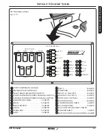
cap. There is a 10 amp reset breaker button located 

on the breaker panel located under the helm on the 

control station which protects the receptacle in the 

glove box. The galley and mid cabin receptacles are 

protected by breakers on the DC breaker panel. 


NOTICE

DO NOT insert a cigarette lighter into the 12V 

receptacles. Damage to the unit and system 

may occur.

DO NOT use accessories that exceed the rated 

capacity of the circuit (10 Amps).

!

CAUTION

Summary of Contents for CONQUEST 345

Page 1: ...eration Helm Seat cover and seating operation Battery ies Mercury s AGM CCA requirements Interior exterior boat inspection Bed operation Microwave stove coffee maker operation Bomar port light operati...

Page 2: ...rtplotter operation Spotlight operation Fresh water operation Starting procedures Generator operation Swim ladder operation Gauge function and explanation Trim tab operation Head system operation VHF...

Page 3: ...The mission of Boston Whaler is to provide consumers with the safest highest quality most durable boats in the world 345 Conquest...

Page 4: ...s and lead which are known to the State of California to cause cancer and birth defects or other reproductive harm To minimize exposure avoid breathing exhaust service your vessel in a well ventilated...

Page 5: ...o provide you with all the information and assistance that you require Information and assistance is also available at our corporate website www bostonwhaler com On our website you will find informati...

Page 6: ...to illustrate the unique characteristics of the Boston Whaler His most famous demonstration was captured in 1961 by Life Magazine The series of photographs showed the boat underway the boat being sawe...

Page 7: ...derations 1 9 Emergency Situations 1 10 Medical Emergency 1 10 Water Rescue 1 10 Returning to the Victim 1 10 Making Contact 1 10 Getting Back on Board 1 10 Unassisted Reboarding 1 10 Fire 1 10 Lessen...

Page 8: ...30 Installation 2 30 To Remove Canvas 2 31 Bow Thruster 2 32 To Operate the Bow Thruster 2 32 Joystick Piloting Option 2 33 Theft Deterrent System Option 2 34 Helm Area Seating 2 35 Captain s Chair 2...

Page 9: ...3 27 ELCI Equipment Leakage Circuit Interrupter 3 28 Shore Power Operation 3 28 Single Cord Shore Power 3 30 Shore Power Load Management 3 31 Battery Charging 3 31 Isolation Transformers 3 31 Fire Su...

Page 10: ...stration Card Automatic Charging Relays ACR 4 4 Component Breakers 4 4 Remote Battery Parallel Switches 4 4 DC Distribution Panel 4 5 Main Distribution Panel 4 6 DC Breaker Panel 4 7 AC Electrical Sys...

Page 11: ...on before using it If this is your first boat or you are changing to a type of boat you are not familiar with for your own comfort and safety please ensure that you obtain handling and operating exper...

Page 12: ...holstered items canvas teak and powder coating manufactured or installed by Boston Whaler that are defective in factory materials and or workmanship and are reported within one 1 year from the date of...

Page 13: ...products and parts will be comparable in function and performance to an original product or part and warranted for the remainder of the original warranty period In no event shall any repair or replac...

Page 14: ...The terms and conditions contained herein as well as those of any documents prepared in conjunction with the sale of this vessel may not be modified altered or waived by any action inaction or repres...

Page 15: ...e date of sale to the original retail owner and are not addressed in the specific warranties listed in paragraphs 1 or 4 or set out in the Exclusions paragraph below 3 One Year Limited Warranty onAcce...

Page 16: ...ntation or implication relating to speed range fuel consumption or estimated performance characteristics 12 Any failure or defect caused by an act of nature resulting in damage cost or expense 13 Any...

Page 17: ...n as well as those of any documents prepared in conjunction with the sale of this vessel may not be modified altered or waived by any action inaction or representations whether oral or in writing exce...

Page 18: ...part will be repaired or replaced by Boston Whaler OWNER S WARRANTY RESPONSIBILITIES As the spark ignition marine watercraft owner you are responsible for performance of the required maintenance list...

Page 19: ...r and 7 Investigating a breach or a contravention of a law complying with a subpoena warrant court order or as required or otherwise permitted by law BOSTON WHALER WILL NOT SELLYOUR PERSONAL INFORMATI...

Page 20: ...Squadron Canadian Power and Sail Squadrons Red Cross State Boating Offices Yacht Club Contact the Boat U S Foundation at 1 800 336 2628 or go to www boatus com foundation Outside of North America cont...

Page 21: ...xix 345 Conquest THIS PAGE INTENTIONALLY LEFT BLANK...

Page 22: ...precautions are not all inclusive Always use common sense in the operation of your boat DANGER Denotes an immediate hazard exists that WILL result in severe personal injury or death Denotes informati...

Page 23: ...courses or go to www boatus com foundation on the internet Get hands on training on how to operate your boat properly In Addition Maintain your boat and its safety and other systems as recommended in...

Page 24: ...nal hazards such as rocks sand bars or dangerous currents to name a few Your passengers are relying on you to operate and maneuver the boat safely so that they are not in danger of going overboard If...

Page 25: ...AZARD Wet decks are slippery Wear proper footwear and use extreme caution on wet surfaces WARNING Death or serious injury can result if you fail to observe these safety rules Anyone who controls the b...

Page 26: ...day and night use on board At least three 3 U S C G approved pyrotechnic devices marked with date showing service life must be carried be readily accessible in serviceable condition and not be expire...

Page 27: ...TO LET FRESH AIR CIRCULATE OPERATING AT SLOW SPEED OR DEAD IN WATER Examples of accumulation of CO Fig 1 6 1 WINDS BLOWING EXHAUSTS TOWARD BOAT OCCUPANTS Fumes from engine s Generator s and other equi...

Page 28: ...5 seconds Maintenance Avoid spraying liquids directly on alarm DANGER Even in rainy cold weather ventilation must be maintained to avoid Carbon Monoxide poisoning You will get wet and or cold Be sure...

Page 29: ...ne that will suit your purpose Type I Off shore Life Jacket is considered the most buoyant it is designed to turn an unconscious person face up Use in all types of waters where rescue may be slow part...

Page 30: ...Modify speed in keeping with weather sea and traffic conditions Instruct passengers on location and use of safety equipment and procedures Instruct passengers on the fundamentals of operating your bo...

Page 31: ...C Emergency Situations Making contact Stop or slow the boat and circle toward the person overboard Try to approach heading into the wind or into the waves Keep person overboard constantly in sight Whe...

Page 32: ...ase of the fire If the fire is in an enclosed compartment and you have an automatic extinguisher for the compartment wait 15 min before opening the compartment Have an extinguisher handy in case of a...

Page 33: ...signals for day use and three for night use Some pyrotechnic devices such as red flares meet both day and night use requirements Store pyrotechnic signals in a cool dry location An orange or red wate...

Page 34: ...CY PAN PAN PAN PAN PAN PAN pronounced PAHN PAHN used when a person or vessel is in some jeopardy less than indicated by a MAYDAY call SAFETY SECURITY SECURITY SECURITY pronounced SAY CURE IT AY used f...

Page 35: ...ze and respect diving flags Keep at least 30 meters 100 ft away Diver s Flags Fig 1 14 2 RED WHITE BLUE CODE ALPHA FLAG SPORT DIVER S FLAG WHITE If you encounter fog determine your position set a safe...

Page 36: ...s 25 m p h it takes only 5 seconds to overtake a fallen skier who was 60 meters 200 feet in front Ski only in areas where skiing is permitted Observe local restrictions on length of tow line Learn the...

Page 37: ...ause it to backlash into the cockpit PERSONAL INJURY HAZARD Use transom tow ring only to pull water skiers Unless specified by the manufacturer any other use such as parasailing kite flying towing oth...

Page 38: ...while docking or in heavy seas strong current or high winds Passengers and crew may lose balance and the boat may lose steering control Should the operator fall out of the boat at planing speed it ma...

Page 39: ...very slowly and post a lookout If an object is struck or if you run aground Shut the engine OFF Check the hull for damage Check propeller for damage If aground consider the bottom grade before moving...

Page 40: ...Guard escort vessel on VHF FM channel 16 Observe and avoid all security zones Avoid commercial port areas especially those that involve military cruise line or petroleum facilities Observe and avoid...

Page 41: ...fter handling the substances above WARNING 1 2 3 PROP 65 HANG TAG 1795087 HANG TAG W JOYSTICK LABEL KIT OPTION 2121785 BRIDGE CLEARANCE OPTION 2027713 Replacement Part No California residents only Thi...

Page 42: ...ED 5 3 Warning Label Locations Cont d Warning Label Locations Cont d Fig 1 21 1 CAUTION MRP 2027713 BRIDGE CLEARANCE UPPER TOWER 17 FEET W OUTRIGGERS 23 FEET WARNING Before activating Skyhook 1 Check...

Page 43: ...l Call your Boston Whaler dealer for replacement labels NOTICE 1 3 4 5 6 Avoid serious injury or death from fire or explosion resulting from leaking fuel Inspect system for leaks at least once a year...

Page 44: ...DIRECTLY OVERBOARD IS FOR USE WHERE APPROVED ONLY WARNING co co co co co co co co co co co co co co co co co co co co co co co co co co co co NW 205 05 Carbon monoxide CO can cause brain damage or de...

Page 45: ...damaged or unreadable label Call your Boston Whaler dealer for replacement labels NOTICE WARNING ROTATING PROPELLER MAY CAUSE SERIOUS INJURY OR DEATH DO NOT APPROACH OR USE LADDER WHEN ENGINE IS RUNN...

Page 46: ...RBOARD DISCHARGE 2063381 DISCHARGE OF OIL 2063375 PLATE BATTERY LOCATIONS 2133293 PLATE BATTERY LOCATIONS JOYSTICK OPTION 2133294 Replacement Part No It is important to replace any damaged or unreadab...

Page 47: ...ING OPERATION PUMP LIFT POINT SLING LOCATION ENGINE START ENGINE STOP FUEL LEVEL WARNING ELECTRICAL HAZARD NO OPEN FLAME NO SMOKING FIRE RISK ROTARY CONTROL WIDTH OF SYMBOL INDICATES INCREASE FRESH WA...

Page 48: ...OATS WOVEN GLASS MATTING Boston Whaler hulls are constructed with our patented Unibond construction process This involves foam injection into a closed mold system where the foam expands to fill all vo...

Page 49: ...l Organization for Standardization directives An Australian Builder s Plate means that your Boston Whaler has been certified with safety standards set by the National Marine Safety Committee Certifica...

Page 50: ...gine weight of 2100 LBS 953 kg NOTICE NOTICE The 345 Conquest is category B Certification Design Category A A recreational craft given design category A is considered to be designed for winds that may...

Page 51: ...ptional equipment and loading of the boat will affect the draft measurements Follow the recommendations regarding the maximum amount of weight your boat can safely carry 1 Exceeding this weight will a...

Page 52: ...ult in serious injury or death especially if the boat is in motion or in rough seas Keep the accommodation deck clean so if movement is necessary it will be free of obstruction DANGER Gelcoat surfaces...

Page 53: ...2 6 1 NOTE Hardtop removed for clarity Recommended Passenger Locations RECOMMENDED SEATING while moored at idle or at speed under 5 mph RECOMMENDED ON PLANE LOCATIONS NEVERallowpassengerstoride in an...

Page 54: ...on of Thru Hull Fittings 1 2 3 4 5 6 6 1 2 3 STARBOARD DECK DRAINS GENERATOR EXHAUST STARBOARD FISHBOX PUMP OUTLET HIGH WATER BILGE PUMP DISCHARGE SHOWER SUMP DISCHARGE COCKPIT A C COCKPIT SINK ICE BU...

Page 55: ...pperflapsshouldbecheckedforpropersealannually When the boat is in the water the underwater fittings can be checked for dripping It is recommended that the underwater fittings be removed cleaned and re...

Page 56: ...ERS 3 TRIPLE MERCURY 4 STROKE ENGINES EXPANDABLE SWIM LADDER WITH COVER GRAB RAIL TRANSOM SHOWER W HOT AND COLD WATER FOLDAWAY STERN BENCH SEAT FOLDAWAY TROLLING SEAT OPTION FRESH WATER FILL DECK PLAT...

Page 57: ...SUPPRESSION INDICATOR LIGHT CONSOLE DRAIN START STOP SWITCH STAINLESS STEEL STEERING WHEEL 11 12 13 14 16 17 18 BOW THRUSTER TOGGLE CONTROL STEREO REMOTE RAYMARINE SMARTPILOT TM AUTOPILOT OPTION SMART...

Page 58: ...RODHOLDERS 3 WASTE PUMPOUT DECK PLATE RAW WATER WASHDOWN FAUCET 12V 30 AMP DC RECEPTACLE FOR ELECTRIC REELS AND OR DOWNRIGGERS P S General Layout Cockpit Fig 2 11 1 2 3 4 5 6 7 8 9 10 1 2 3 4 5 6 7 8...

Page 59: ...IC SINGLE BURNER STOVE OPTION REFRIGERATOR FREEZER 12 V 120V GALLEY SINK W HOT COLD WATER FAUCET STORAGE TRASH RECEPTACLE 3 4 5 6 7 10 11 12 13 14 15 8 9 16 17 V BERTH DINETTE ISLAND BED ACTUATION AND...

Page 60: ...formation ROD HOLDER REEL LATCH FRESH WATER REEL ADAPTER HEAD LIGHT SWITCH General Layout Forward Cabin Con t Fig 2 13 1 1 2 3 2 STARBOARD FWD 1 2 3 4 5 7 8 4 ISLAND BED ACTUATION SWITCH CABIN TABLE A...

Page 61: ...NET STORAGE SHOWER FLOOR DRAIN VACU FLUSH TOILET OVERBOARD DISCHARGE VACU FLUSH PANEL 3 4 5 6 7 8 9 10 General Layout Mid Cabin Fig 2 14 1 1 2 EQUIPMENT ACCESS TASK LIGHT P S PREMIUM STEREO SPEAKER OP...

Page 62: ...INE 4KW OPEN ARRAY RADAR OPTION GPS OPTION SPOTLIGHT WITH REMOTE OPTION DUAL TRUMPET HORNS VHF RADIO ANTENNA OPTION General Layout Hardtop Fig 2 15 1 1 2 4 5 3 6 7 8 10 13 9 14 11 12 DOME LIGHTS STERE...

Page 63: ...orward and aft and rotated 360o The port companion aft seat can be adjusted to accommodated forward as well as aft facing seating By utilizing the filler cushion the companion area can be converted in...

Page 64: ...11 13 12 16 19 18 20 21 21 WINDSHIELD WASHER PORT WIPER CENTER WIPER STARBOARD WIPER NAV LIGHTS ACCENT LIGHTS COURTESY LIGHTS MAP LIGHTS FLOOD LIGHTS UNDERWATER LIGHTS OPTION PORT FISHBOX PUMP STARBOA...

Page 65: ...d will hear a click when neutral is engaged Digital Throttle Shift DTS Shift controls into NEUTRAL before starting engine Shift only when engine is at idle Reversing at high speeds can cause flooding...

Page 66: ...the three engines REFERTOTHEENGINEMANUFACTURER SMANUAL INYOUROWNER SMANUALPACKETFORCOMPLETE INSTRUCTIONS INFORMATION AND WARRANTY Shadow Mode Technology Power Trim Operation The power trim tilt system...

Page 67: ...ket It is recommended to have the engines trimmed all the way down or in for best visibility and reduced planing time Once on plane adjust trim angle for maximum engine RPM and efficiency REFERTOTHEEN...

Page 68: ...achieved by either of two methods NOTE It is preferred to have the engines in neutral position when performing a station transfer If conditions do not allow the remote controls to be placed in a neutr...

Page 69: ...r 2 Adjust the control handles to the desired throttle and gear positions Avoid serious injury or death from loss of boat control The boat operator should NEVER LEAVE THE ACTIVE STATION while the engi...

Page 70: ...d on the console switch panel marked NAV LTS See page 2 17 controls the navigation and anchor lighting In the Navigation Lights position See below the port red and starboard green lights and all aroun...

Page 71: ...TO CLOSE PORT AFT SEAT BACK HINGED CUTTING BOARD HEAT SHIELD STORAGE LID 5 6 2 7 8 2 2 7 8 9 5 6 4 1 3 5 9 Companion Lounge Footrest The entertainment station on your boat includes a hide away footre...

Page 72: ...n automatic shut off switch located at the back of the grill cover When the cover is closed the Please read and understand the safety precautions found in the Kenyon Custom Electric Grill owner s manu...

Page 73: ...nk with pull out hot and cold water faucet 120V receptacle located on the starboard wall behind the helm chair integrated cup holders and storage compartment Fusion stereo remote insulated cooler and...

Page 74: ...erside of the access hatch and set aside in the cockpit Remove the pedestal from its storage and place it upright in the receiver plate located on the deck in the cockpit Place table top on the top of...

Page 75: ...S VENT WASHER PORT WIPER CNTR WIPER STBD WIPER ACNT LTS CTSY LTS MAP LTS FLOOD LTS U W LTS FISH BOX P FISH BOX S LIVEWELL L WELL LT WINDLASS UP DOWN If equipped the two 2 12V 30 amp electrical recepta...

Page 76: ...rigger mounting base plates that can be used it is important that you consult with your salesperson to find the mounting base that will best suit your application CAUTION NOTICE If the optional port f...

Page 77: ...can be difficult since rough water or wakes can cause you or your passengers to lose their balance while attempting to install or remove canvas panels For your safety and ease of installation or remo...

Page 78: ...ther fresh air must circulate through the boat to avoid carbon monoxide poisoning See page 1 6 of this manual for additional important information regarding carbon monoxide When zippers are new they c...

Page 79: ...l suction is created when in use WARNING Bow Thruster Fig 2 32 1 Waterline Bow Thruster Bow Thruster Location Fig 2 32 2 When the desired boat movement has been achieved return the joystick to the cen...

Page 80: ...technology is the latest enhancement in vessel control providing effortless maneuverability The joystick Piloting system replaces the traditional bow thruster set up Joystick Piloting takes the stres...

Page 81: ...heading adjustments can be made with a tap on the joystick 10 degree adjustments can be accomplished using the control panel Trips with multiple stops between the starting point and final destination...

Page 82: ...to provide smooth action and easy adjustment Helm Area Seating Adustable Captain s Chair Fig 2 35 1 FLIP UP THIGH BOLSTER LIFT AWAY ARM REST 1 2 The port lounge features an adjustable aft back which...

Page 83: ...the latchandreleasetheknobs allowing the pins to engage the reel Place Rod Tips in Holder Pull down on the spring loaded insert Place the rod tip in the holder Return the insert to the closed positio...

Page 84: ...uipment or injury to persons on board CAUTION The microwave located above the galley in the port cabin is powered by the generator or shore power and is protected by a 20 amp breaker on the AC breaker...

Page 85: ...stereo unit is located on the wall below the TV There are three 3 stereo remote controls which are located on the control console the aft wall of the starboard wet bar and in the cabin port of the ma...

Page 86: ...ANUAL IN YOUR OWNER S MANUALPACKET FOR COMPLETE INSTRUCTIONS INFORMATION AND WARRANTY MP3 Operation Fig 2 39 1 2 1 TV DVD Player To Operate DVD Player The DVD player is powered by the batteries Turn o...

Page 87: ...ade replacement ANCO wiper blades 3 32 inches Windshield Wiper Washer Switch Fig 2 40 1 Electric Sun Shade Option If equipped the electrically actuated cockpit sun shade can be deployed or retracted b...

Page 88: ...ering the boat DO NOT use the bow and stern eyes for lifting the boat Whether you are lifting your boat out of the water for routine maintenance or long term storage consider the following If you are...

Page 89: ...Chain Cable There is a safety chain cable that attaches to the bow eye and will keep the boat from sliding off the trailer in the event that the winch strap or cable breaks Hook this up first Trailer...

Page 90: ...R S MANUAL PACKET FOR PROPER ENGINE SUPPORT WHILE TRAILERING NOTICE CAUTION DO NOT rely on the power trim tilt system or tilt support lever on your outboards to maintain proper ground clearance for tr...

Page 91: ...ur boats keel can be obtained by contacting your dealer or Boston Whaler Out of Water storage Keel Stands Fig 2 44 1 KEEL STAND 3 7812 3 1512 7812 1414 CAUTION In addition to the three 3 keel stands u...

Page 92: ...60 60 60 CAUTION In addition to the six 6 wood blocks use a minimum of four 4 side stands two 2 placed at port and two 2 placed at starboard EACH WOOD BLOCK MUST CONTACT THE HULL FOR A MINIMUM LENGTH...

Page 93: ...2 46 Section 2 General Information 345 Conquest THIS PAGE INTENTIONALLY LEFT BLANK...

Page 94: ...GE or AUX bilge See figure 2 17 1 the operator can energize the pumps regardless of the position of the float switches The aft pump discharges water overboard by way of a thru hull fitting on the aft...

Page 95: ...If water does not come out of the discharge hose 1 Remove the motor module to see if the impeller rotates with the power on 2 Remove any debris that may have accumulated in the impeller section or st...

Page 96: ...er aft seat cushion Gray water from the galley shower vanity condensate from the air conditioners and water from the water heater all drain into the sump The sump contains its own automatic pump to di...

Page 97: ...below the pickup tube and the ullage area that has been incorporated into your tank It is recommended that you follow all instructions regarding the filling of fuel tanks Please take time to Leaking f...

Page 98: ...istribution System The fuel is delivered from the tank to the engine through the Fuel Demand Valve FDV anti siphon valve and the fuel line The FDV prevents the built up pressure inside the tank from b...

Page 99: ...eling practices The following suggestions will help keep you safe from static electricity while refueling your boat NEVERfuelyourboatinunsafeconditionssuch as suspended on a sling or in a situation th...

Page 100: ...ges in temperature as well as limiting exposure of the ethanol in the fuel to humidity and condensation Phase Separation Humidity and condensation create water in your fuel tank which can adversly eff...

Page 101: ...air temperature moves up and down This condensation could potentially become a problem Storage REFERTOTHEENGINEMANUFACTURER SMANUAL INYOUROWNER SMANUALPACKETFORCOMPLETE INSTRUCTIONS AND WARRANTY Powe...

Page 102: ...he gear shift throttle control is in the neutral position The engine will not start if the control lever is in any other position than NEUTRAL Be sure the emergency stop switch See figure 1 14 1 is in...

Page 103: ...activated by turning the engines off and re starting TRIM UP NEUTRAL TROLL SYNC TRANSFER 1 LEVER THROTTLE ONLY DOCK PORT CENT ER STBD N N SYN C TRA NSF ER 1 LEV ER THR OTT LE ONL Y DOC K PORT CENTER...

Page 104: ...only use it seasonally it is recommended that you follow the disinfecting practice before using it NOTICE The freshwater system on your boat includes a 45 gal 170 3 L fresh water tank a pump and a di...

Page 105: ...r if this has been done Filling the Tank 1 12V DC 8 10 12 16 VOLTMETER 14 OFF OFF OFF TV CABIN OH LTS CABIN ACCENT BATTERY TEST OFF OFF OFF OFF OFF OFF OFF CABIN REFRIG BERTH CABIN CABIN STEREO FRESH...

Page 106: ...otable water 6 Now the system is ready for use fill with potable water This should be done annually or before using the system if it has been laid up for an extended amount of time NEUTRAL TROLL SYNC...

Page 107: ...the hose when leaving the boat for an extended period of time Water Heater Make sure the fresh water tank is full before operating the water heater Operating water heater empty will cause damage to s...

Page 108: ...Manually operate the pressure relief valve at least once a year This must be done when the water in the storage tank is cool The system must be flushed several times per year which will prolong the l...

Page 109: ...desired Half Cycle 7 5 minutes Push the start button TWICE The system will cycle for 7 5 minutes per engine Push the start button ONCE to stop in the middle of cycle if desired Fill the livewell by p...

Page 110: ...view Operation Raw Water System Fig 3 17 1 1 2 3 4 5 6 RAW WATER INTAKE RAW WATER PUMP TO 40 GAL 151 4 L LIVEWELL LIVEWELL FLOW CONTROL VALVE WASHDOWN HOSE CONNECTOR LIVEWELL FILL CLOSED OPEN 1 2 3 4...

Page 111: ...ssel to dump plastic trash anywhere in the ocean or navigable waters of the United States NOTICE Your boat is equipped with a waste disposal system located in the head in the forward cabin The system...

Page 112: ...m can be emptied by means of dockside pumpout preferred through the Waste deck plate on the port transom The system also provides for overboard discharge by way of a macerator lockable discharge seaco...

Page 113: ...EL DISCHARGE PUMP VAC PUMP FULL HALF EMPTY ON EXHAUST FAN INT LIGHTS EXH FAN VAC PUMP DISCH PUMP 1 2 3 4 5 6 7 3 4 5 6 7 After long periods of non use the macerator pump may not turn freely Regular us...

Page 114: ...dors associated with waste operations through the bilge vent on the aft of the transom Avoid overflowing the holding tank If the FULL light is lit on the discharge control panel located in the head yo...

Page 115: ...8 18 000 BTU REVERSE CYCLE AIR HANDLER 12 000 BTU REVERSE CYCLE AIR HANDLER COLD AIR RETURN HELM AIR VENT CONSOLE AIR VENTS CABIN AIR VENT HEAD AIR VENT 9 10 11 FWD OPEN CLOSED The helm deck A C unit...

Page 116: ...MANUFACTURER S MANUAL IN YOUR OWNER S MANUAL PACKET FOR COMPLETE INSTRUCTIONS AND WARRANTY OFF AUTO MODE COOL HEAT AUTO DEHUMIDIFY A C Control Panel Fig 3 23 1 Maintenance The air conditioning unit is...

Page 117: ...N MONOXIDE can cause severe NAUSEA FAINTING or DEATH The exhaust system must be leakproof and routinely inspected EXPLOSIVE FUEL VAPORS Can cause SEVERE INJURY or DEATH Use extreme care when handling...

Page 118: ...the DC Breaker Panel See page 4 7 and operate the blower for 4 minutes Manually check the bilge for fuel or fuel vapor NOTE Refer to the manufacturer s Operations Manual for a Pre Start Checklist OPE...

Page 119: ...l have complete instructions on bleeding the fuel system should it be needed Under no circumstances override the source select system WARNING GENERATOR SHORE 1 MAIN GEN BRIDGE SHORE 2 MAIN ON ON ON ON...

Page 120: ...d gunwale The AC Main Breaker panel for the shore power system is located on the aft wall of the console interior Shore Power Shore Power Receptacles Fig 3 27 1 1 2 SHORE POWER INTERMEDIATE BREAKER EL...

Page 121: ...O NOT USE CONSULT A QUALIFIED ELECTRICIAN FOR REPAIR OR REPLACEMENT Be certain that the shore power main switch is turned OFF before connecting the power cord cordset Connect the cordset to the boat i...

Page 122: ...is dry before plugging into the dock power outlet OFF OFF OFF OFF OFF OFF OFF OFF OFF OFF MAIN GENERATOR AFT CHARGER FWD CHARGER WATER HEATER COCKPIT OUTLETS COCKPIT REFRIG COCKPIT A C COCKPIT FREEZER...

Page 123: ...RESE T TEST WARNI NG TEST BEFORE EACH USE OWE R FAUL T ODUL E RESE T TEST WARNING TEST BEFORE EACH USE OWE R FAUL T ODUL E OFF OFF OFF OFF OFF OFF OFF OFF OFF OFF OFF OFF MAIN GENERATOR AFT CHARGER F...

Page 124: ...he operator will need to power off certain appliances based on load requirements shore power connections and or generator operation To obtain the most power for your appliances it is best to use the G...

Page 125: ...ble allow the compartments vapor to dissipate before opening the hatch NEVER attempt to modify or disassemble any components of this system If the system has been discharged have a qualified technicia...

Page 126: ...7 To position the outriggers Raising or lowering Turn the cam knob counterclockwise to loosen position the outrigger up or down to the desired position and tighten the cam by turning the knob clockwi...

Page 127: ...ning to a planing operation While accelerating there is some loss of forward visibility before the boat is on plane the trim tabs can be used to adjust for forward visibility while transitioning to a...

Page 128: ...nspect the planes and hinges for marine growth and remove as necessary Auto Glide Boat Control System Option If equipped the Auto Glide uses engine and GPS data to drive your boat to the most efficien...

Page 129: ...on the key pad REFER TO THE MANUFACTURER S MANUAL IN YOUR OWNER S MANUAL PACKET FOR COMPLETE INSTRUCTIONS AND WARRANTY If equipped the Active trim panel is located on the forward hardtop above the con...

Page 130: ...he anchor windlass is lost A anchor lanyard secures the anchor when stowed and the boat is underway The windlass is protected by a 100 amp circuit breaker located on the battery switch panel See page...

Page 131: ...e anchor windlass switch on the helm when possible Use care when operating the anchor windlass with the hand held remote DANGER Operating From the Helm LOWERING Pushing the top part of the switch down...

Page 132: ...heel The star socket located off center is used for retrieving and lowering the anchor Turning the handle counterclockwise will allow you to lower the anchor while turning it clockwise will raise it W...

Page 133: ...formance 345 Conque st Bow Height Water Depth Rode Proper Anchoring Fig 3 40 1 Rode length bow height water depth X Scope Be careful that the trailing lines do not foul in the propeller CAUTION The ro...

Page 134: ...go The anchor will usually break out when the rode becomes vertical Coil lines to let them dry before stowing Weighing the Anchor There is no best way to set an anchor Experiment to see how it perform...

Page 135: ...located behind an access door on the port wall of the companion lounge and the forward wall under the helm seat house and secure the batteries See charts below NOTICE Always store the batteries in the...

Page 136: ...along with a battery charger located under the forward cabin berth Access to the thruster equipment can be made through the hatch in the floor Bow Thruster Battery trays Your batteries should always...

Page 137: ...drained to zero charge before recharging Battery Switch Panel Fig 4 3 1 BATTERY SWITCHES PORT CENTER STBD THRUSTER PARALLEL 12V DC DISTRIBUTION O OFF ON 1 O OFF ON 1 O OFF ON 1 O OFF ON 1 O OFF ON 1...

Page 138: ...ng a charge the system will draw power from the center and house batteries This allows all boat functions to be run without affecting the port or starboard battery Remote Battery Parallel Switches The...

Page 139: ...SWITCH ACR CONTROL R 2 6 PORT COMPANION LOUNGE MAIN BATTERY SWITCHES BOW THRUSTER BATTERY SWITCH PORT CENTER BATTERIES PARALLEL SWITCH CENTER STBD BATTERIES PARALLEL SWITCH UNSWITCHED MAIN 50 AMPS MAI...

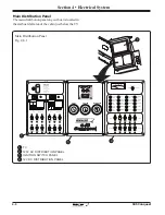
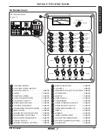
Page 140: ...KPIT COCKPIT HOUSE THRUSTER NAV ANC LIGHTS COURTESY LIGHTS MAP LIGHTS FLOOD LIGHTS L W LIGHTS HORN WINDLASS CONTROL SHADE ACTUATOR SHADE CONTROL CO MONITOR W S WIPER PORT W S WIPER CENTER W S WIPER ST...

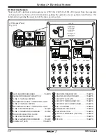
Page 141: ...T OFF ACC ON S T A R T CENTER STARBOARD 12V DC 8 10 12 16 VOLTMETER 14 OFF OFF OFF TV CABIN OH LTS CABIN ACCENT BATTERY TEST OFF OFF OFF OFF OFF OFF OFF CABIN REFRIG BERTH CABIN CABIN STEREO FRESH WA...

Page 142: ...BIN REFRIG CABIN A C SHORE POWER 1 REVERSE SHORE POWER 2 REVERSE MAIN GEN BRIDGE 120 V AC BLOWER WARNING GASOLINE VAPORS CAN EXPLODE BEFORE STARTING GENERATOR CHECK FOR GASOLINE VAPORS OPERATE BLOWER...

Page 143: ...reakers is a fire hazard Use fuses and breakers having the same amperage rating as the original or as specified WARNING 12 Volt Accessory Receptacles Your boat is equipped with six 6 12 volt receptacl...

Page 144: ...on the starboard side of the cabin entry door Figure 4 4 1 The cabin lighting is protected by a breaker on the DC breaker panel located on the starboard side of the cabin See figure 4 7 1 The CABIN O...

Page 145: ...receptacles RESET TEST Persons with heart problems or other conditions which may make them susceptible to electric shock may still be injured by ground faults on circuits protected by the GFI recepta...

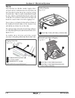
Page 146: ...tarboard frame of the hardtop which terminates in the console at one end and the electronics box at the other The optional upper station electrical wiring and hoses are routed through the port and sta...

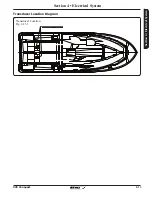
Page 147: ...4 13 Section 4 Electrical System 345 Conquest Section 4 Electrical System Transducer Location Fig 4 13 1 Transducer Location Diagram...

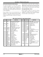
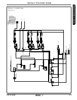
Page 148: ...RD FISHBOX PUMP 12 AWG BRN VIO FORWARD FISHBOX PUMP 12 AWG BRN YEL LIVEWELL PUMP HIGH CURRENT 12 AWG BRN BLU PORT FISHBOX PUMP 12 AWG BLK GROUND 12 AWG RED 12V MAIN 14 AWG BLK GROUND 14 AWG BLK YEL ST...

Page 149: ...4 15 Section 4 Electrical System 345 Conquest Section 4 Electrical System Batteries Standard Boat Fig 4 15 1...

Page 150: ...4 16 345 Conquest Section 4 Electrical System Batteries Joystick Steering Option Fig 4 16 1...

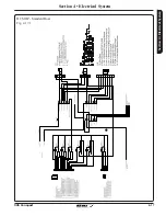
Page 151: ...4 17 Section 4 Electrical System 345 Conquest Section 4 Electrical System DC MDP Standard Boat Fig 4 17 1...

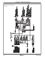
Page 152: ...4 18 345 Conquest Section 4 Electrical System DC MDP Joystick Steering Fig 4 18 1...

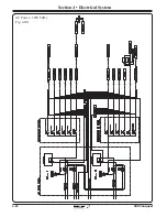
Page 153: ...4 19 Section 4 Electrical System 345 Conquest Section 4 Electrical System AC Power 120V 60Hz Schematic Fig 4 19 1...

Page 154: ...4 20 345 Conquest Section 4 Electrical System AC Power 220V 50Hz Fig 4 20 1...

Page 155: ...4 21 Section 4 Electrical System 345 Conquest Section 4 Electrical System Courtesy Accent Lights Fig 4 21 1...

Page 156: ...4 22 345 Conquest Section 4 Electrical System Cabin O H and Accent Lights Fig 4 22 1...

Page 157: ...4 23 Section 4 Electrical System 345 Conquest Section 4 Electrical System NAV Map Flood and Underwater Lighting Fig 4 23 1...

Page 158: ...4 24 345 Conquest Section 4 Electrical System Wipers and Washers Fig 4 24 1...

Page 159: ...4 25 Section 4 Electrical System 345 Conquest Section 4 Electrical System Spotlight Horn Shureshade and Windshield Vent Fig 4 25 1...

Page 160: ...4 26 345 Conquest Section 4 Electrical System Waste System Fig 4 26 1...

Page 161: ...4 27 Section 4 Electrical System 345 Conquest Section 4 Electrical System Windlass Fig 4 27 1...

Page 162: ...4 28 345 Conquest Section 4 Electrical System Trim Tabs Fig 4 28 1...

Page 163: ...4 29 Section 4 Electrical System 345 Conquest Section 4 Electrical System Bow Thruster Fig 4 29 1...

Page 164: ...4 30 345 Conquest Section 4 Electrical System Courtesy Outlets Blower Extinguisher and 30A reel Outlets Fig 4 30 1...

Page 165: ...4 31 Section 4 Electrical System 345 Conquest Section 4 Electrical System Pumps Sheet 1 Fig 4 31 1...

Page 166: ...4 32 345 Conquest Section 4 Electrical System Pumps Sheet 2 Fig 4 32 1...

Page 167: ...4 33 Section 4 Electrical System 345 Conquest Section 4 Electrical System Pumps Sheet 3 Fig 4 33 1...

Page 168: ...4 34 345 Conquest Section 4 Electrical System V Berth Schematic Fig 4 34 1...

Page 169: ...4 35 Section 4 Electrical System 345 Conquest Section 4 Electrical System Shore Power 120V Schematic Fig 4 35 1...

Page 170: ...4 36 345 Conquest Section 4 Electrical System Shore Power 230V 50HZ Fig 4 36 1...

Page 171: ...4 37 Section 4 Electrical System 345 Conquest Section 4 Electrical System Stereo Basic Option Fig 4 37 1...

Page 172: ...4 38 345 Conquest Section 4 Electrical System Stereo Premium Option Fig 4 38 1...

Page 173: ...4 39 Section 4 Electrical System 345 Conquest Section 4 Electrical System Stereo Upper Station Option Fig 4 39 1...

Page 174: ...4 40 345 Conquest Section 4 Electrical System Heater CO Monitor Fig 4 40 1...

Page 175: ...4 41 Section 4 Electrical System 345 Conquest Section 4 Electrical System Generator 120V 60Hz Fig 4 41 1...

Page 176: ...4 42 345 Conquest Section 4 Electrical System Generator 230V 50Hz Fig 4 42 1...

Page 177: ...4 43 Section 4 Electrical System 345 Conquest Section 4 Electrical System Port AC Harness Fig 4 41 1...

Page 178: ...4 44 345 Conquest Section 4 Electrical System STBD AC Harness Fig 4 42 1...

Page 179: ...4 45 Section 4 Electrical System 345 Conquest Section 4 Electrical System Port DC Harness Fig 4 43 1...

Page 180: ...4 46 345 Conquest Section 4 Electrical System STBD DC Harness Fig 4 44 1...

Page 181: ...4 47 Section 4 Electrical System 345 Conquest Section 4 Electrical System Battery Layout Fig 4 45 1...

Page 182: ...4 48 345 Conquest Section 4 Electrical System Windlass Harness Fig 4 46 1...

Page 183: ...4 49 Section 4 Electrical System 345 Conquest Section 4 Electrical System Headliner Harness Fig 4 47 1...

Page 184: ...4 50 345 Conquest Section 4 Electrical System Bow Thruster Harness Fig 4 48 1 Hardtop Harness Fig 4 48 2...

Page 185: ...evere you may need to enlist the services of a professional hull cleaning company Check with your Boston Whaler dealer for recommendationsona compatible rubbingcompound for your boat or a professional...

Page 186: ...ll take some time The effect of osmotic pressure allows water to impregnate below the gel coat and substrate thus forming a blister Bottom Painting There are risks and dangers inherent with the use of...

Page 187: ...he key to successful hull painting Take extra care and time in preparation before proceeding to paint Begin by scrubbing the surface thoroughly with a stiff brush using an all purpose marine soap and...

Page 188: ...nd coating with a good grade cleaning wax will help maintain the finish Wash with mild soap and cold or lukewarm water Stainless Steel Care NOTICE Masking tape is NOT recommended for the types of pain...

Page 189: ...completely using a soft cloth and mild detergent to remove salt particles Hosing alone will not dislodge all particles DO NOT allow soap to dry as it may cause stains on coated surfaces Make sure to...

Page 190: ...lution Dry with a soft lint free cloth or towel More difficult stains can be cleaned using rubbing alcohol isopropyl alcohol Rinse cleaned area with fresh water and dry with a clean soft lint free clo...

Page 191: ...n be used with a nonabrasive soap or detergent A soft sponge kept clean for this purpose is excellent Blot dry with a clean damp chamois NOTICE Never use a dry cloth or duster or glass cleaning soluti...

Page 192: ...long periods of intense sunlight FOR MORE INFORMATION CONTACT BOSTON WHALER CUSTOMER SERVICE 1 877 294 5645 Place hot items directly on the surface Subject to sudden temperature changes hot to cold co...

Page 193: ...on the lower unit of your engines Replace if half or more of the zinc is missing NOTICE Fill the tank completely 100 full and add fuel stabilizer and conditioner following the manufacturer s recommen...

Page 194: ...negative first Remove the battery from the boat Cleantheterminalendsofthecablesandbattery terminals with a solution of baking soda and water Rinse thoroughly with clean water Apply a coat of grease o...

Page 195: ...e clear and free of debris and plugs are removed Store the engine in an upright position to promote adequate drainage of water Drainage Remove any valuables or anything that can be easily removed from...

Page 196: ...event you wish to add equipment to your boat which requires you to penetrate the deck with fasteners the diagrams on the following pages illustrate the size location and type of the reinforcement avai...

Page 197: ...2X8 D 26 PLYWOOD 7X9 D 27 PLYWOOD 8X10 D 28 PLYWOOD 3X7 D 29 PLYWOOD 6X10 D 30 PLYWOOD 3X8 D 31 PLYWOOD 10X10 32 PLYWOOD 2X7 D 33 PLYWOOD 4X7 5 D 34 PLYWOOD 4X9 25 35 PLYWOOD 9X9 D 36 PLYWOOD 3X4 D 37...

Page 198: ...OD 4X4 DM0444 5 18 PLYWOOD 6X6 DM0474 1 19 PLYWOOD 8X8 DM0483 6 20 PLYWOOD 5X9 DM0472 1 21 PLYWOOD 3X6 DM0434 6 22 PLYWOOD 4X10 DM0467 1 23 PLYWOOD 9X10 DM0487 3 24 PLYWOOD 3 25X9 DM1164 3 25 PLYWOOD...

Page 199: ...NOLIC 8X10 57 PHENOLIC 3X8 D 58 AQUA PLAS 10X 59 AQUA PLAS 5X1 60 PHENOLIC 3X7 D 61 PHENOLIC 3X10 62 PHENOLIC 3X9 D 1 1 1 1 3 3 3 3 3 3 3 3 4 5 7 8 9 10 11 14 14 15 15 16 17 17 19 19 21 21 24 26 26 26...

Page 200: ...50 PHENOLIC 3X7 DM0148 4 51 PHENOLIC 2 75X12 DM0614 4 52 AQUA PLAS 6X8 DM0400 2 53 PHENOLIC 8X10 DM0065 3 54 PHENOLIC 1 75X10 1 55 PHENOLIC 7X10 DM0174 1 56 PHENOLIC 8X10 DM0177 1 57 PHENOLIC 3X8 DM01...

Page 201: ...28 PHENOLI 29 PENSKE 8 30 13 8X23 31 PLYWOO 32 PLYWOO 33 PLYWOO 34 PLYWOO 35 PLYWOO 36 PLYWOO 37 PHENOLI 38 PLYWOO 39 PHENOLI 40 PLYWOO 41 PHENOLI 42 PHENOLI 43 BALSA 2 44 BALSA 1 45 BALSA 2 46 BALSA...

Page 202: ...5X19 DM1195 4 24 PLYWOOD 7X31 20 6371 P139 1 25 PLYWOOD 7X22 327 6371 P138 1 26 PLYWOOD 7X22 327 6371 P137 1 27 PHENOLIC 6X8 5 DM1220 2 28 PHENOLIC 1 5X5 3 29 PENSKE 8X9 DM0141 1 30 13 8X23 5 6371 P0...

Page 203: ...PHENOLIC 3 75X12 82 PHENOLIC 3X8 5 DM0942 83 PHENOLIC 2 25X14 84 PLYWOOD 2X23 DM0592 85 PLYWOOD 3X23 86 PLYWOOD 2X22 75 87 PLYWOOD 1X22 75 88 PHENOLIC 1 75X19 25 DM0554 89 PLYWOOD 1X23 DM0545 90 PLYW...

Page 204: ...LSA 17 875X42 875 6371 P021 1 71 BALSA 32X42 25 6371 P015 1 72 BALSA 9X20 6371 P014 1 73 BALSA 11 75X23 375 6371 P013 1 74 BALSA 22 25X42 25 6371 P012 1 75 PHENOLIC 1 75X3 DM0564 4 76 PHENOLIC 4 625X2...

Page 205: ...5 21 Section 5 Care Maintenance 345 Conquest MAINTENANCE LOG ENGINE SERVICED DATE HOURS BY MAINTENANCE PERFORMED Fill out the log below after scheduled service or maintenance is performed NOTES...

Page 206: ...5 22 Section 5 Care Maintenance 345 Conquest THIS PAGE INTENTIONALLY LEFT BLANK...

Reviews: