2-19
345 Conquest
Section 2 • General Information
Section 2 • General Information
REFER TO THE ENGINE MANUFACTURER’S MANUAL
IN YOUR OWNER’S MANUAL PACKET FOR COMPLETE
INSTRUCTIONS, INFORMATION AND WARRANTY.
RPM. To disengage, return control handle to neutral
and press the “throttle only” button.
1 LEVER
- Pressing the “1 LEVER” button initiates
single lever mode. Single lever mode enables the
throttle and shift functions of all engines to be
controlled by the port control handle. To turn off
single lever mode, shift into neutral and press the
“1 LEVER” button.
With triple engines, the DTS
®
system incorporates
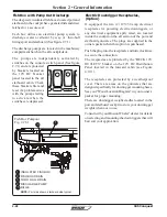
Shadow Mode Technology which enables the center
engine to “shadow” or follow the outboard engines
when the outboard engines are in the same gear.
When the outboard engines are in opposite gears,
as they would be for docking maneuverability, the
center engine automatically defaults to neutral. This
gives the operator greater control when docking.
Auto Sync
®
The unique Auto Sync
®
feature has been designed
to synchronize ALL engines, automatically, when
the port and starboard control levers are within 10
degrees of each other and the engines are running
above 1500 rpm and below 95 percent throttle.
This feature eliminates the need for the levers to be
perfectly aligned in order to synchronize the three
engines.
REFER TO THE ENGINE MANUFACTURER’S MANUAL
IN YOUR OWNER’S MANUAL PACKET FOR COMPLETE
INSTRUCTIONS, INFORMATION AND WARRANTY.
Shadow Mode Technology
Power Trim Operation
The power trim & tilt system allows you to raise and
lower the engine(s) for optimum performance in the
water and for trailering, launching and beaching.
The switches are a momentary type switch; which
means that constant pressure must be applied to the
switch during the raising and lowering cycle.
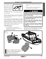
Motor trim, hull trim plane and speed are factors
that affect a boat’s trim angle such that visibility
can be obscured.
NOTICE
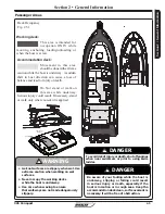
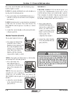
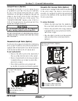
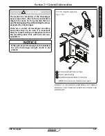
Trim Switch Control Pad
Fig. 2.19.1
Use the trim switch to obtain an ideal boat angle
(in relation to the water surface) for a given load
and water condition. In most cases, best all around
performance is obtained with the engine adjusted
so that the boat will run at a 3° to 5° angle to the
water.
The trim switches are located on a control pad at
the center of the control console. The engines can
be individually trimmed by pressing the appropriate
coordinating switch. All engines can be trimmed at
the same time by pressing the “ALL” switch on the
control pad or the trim switch located on the port
throttle control lever (See fig. 2.18.1).
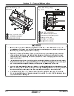
PORT
CENTER
STBD
N
N
SYNC
TRANSFER
1 LEVE
R
THROTTLE
ONLY
DOCK
PORT
CENTER
STBD
N
N
SYNC
TRANSFER
1 LEVER
THROTTLE
ONLY
DOCK
1
2
3
ALL ENGINES TRIM SWITCH
PORT ENGINE TRIM SWITCH
CENTER ENGINE TRIM SWITCH
STARBOARD ENGINE TRIM SWITCH
3
2
4
1
4
Summary of Contents for CONQUEST 345
Page 21: ...xix 345 Conquest THIS PAGE INTENTIONALLY LEFT BLANK...
Page 93: ...2 46 Section 2 General Information 345 Conquest THIS PAGE INTENTIONALLY LEFT BLANK...
Page 150: ...4 16 345 Conquest Section 4 Electrical System Batteries Joystick Steering Option Fig 4 16 1...
Page 152: ...4 18 345 Conquest Section 4 Electrical System DC MDP Joystick Steering Fig 4 18 1...
Page 154: ...4 20 345 Conquest Section 4 Electrical System AC Power 220V 50Hz Fig 4 20 1...
Page 156: ...4 22 345 Conquest Section 4 Electrical System Cabin O H and Accent Lights Fig 4 22 1...
Page 158: ...4 24 345 Conquest Section 4 Electrical System Wipers and Washers Fig 4 24 1...
Page 160: ...4 26 345 Conquest Section 4 Electrical System Waste System Fig 4 26 1...
Page 161: ...4 27 Section 4 Electrical System 345 Conquest Section 4 Electrical System Windlass Fig 4 27 1...
Page 162: ...4 28 345 Conquest Section 4 Electrical System Trim Tabs Fig 4 28 1...
Page 166: ...4 32 345 Conquest Section 4 Electrical System Pumps Sheet 2 Fig 4 32 1...
Page 168: ...4 34 345 Conquest Section 4 Electrical System V Berth Schematic Fig 4 34 1...
Page 170: ...4 36 345 Conquest Section 4 Electrical System Shore Power 230V 50HZ Fig 4 36 1...
Page 172: ...4 38 345 Conquest Section 4 Electrical System Stereo Premium Option Fig 4 38 1...
Page 174: ...4 40 345 Conquest Section 4 Electrical System Heater CO Monitor Fig 4 40 1...
Page 176: ...4 42 345 Conquest Section 4 Electrical System Generator 230V 50Hz Fig 4 42 1...
Page 178: ...4 44 345 Conquest Section 4 Electrical System STBD AC Harness Fig 4 42 1...
Page 180: ...4 46 345 Conquest Section 4 Electrical System STBD DC Harness Fig 4 44 1...
Page 182: ...4 48 345 Conquest Section 4 Electrical System Windlass Harness Fig 4 46 1...
Page 206: ...5 22 Section 5 Care Maintenance 345 Conquest THIS PAGE INTENTIONALLY LEFT BLANK...

